Nissan Juke Service and Repair Manual : Drive pinion
Exploded View
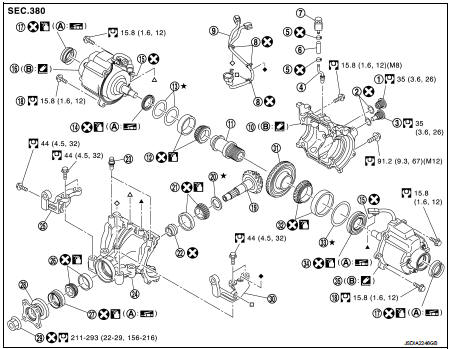
1. Filler plug
2. Gasket
3. Drain plug
4. Breather tube
5. Clip
6. Breather hose
7. Breather
8. sub-harness clip
9. sub-harness
10. Rear cover
11. Center stem
12. Side bearing (right)
13. Side bearing adjusting shim (right)
14. Side oil seal (right)
15. Connector clip
16. Electric controlled coupling (right)
17. Electric controlled coupling oil seal
18. Reamer bolt
19. Drive pinion
20. Drive pinion adjusting shim
21. Pinion rear bearing
22. Collapsible spacer
23. Breather
24. Gear carrier
25. Carrier bracket (right)
26. Pinion front bearing
27. Front oil seal
28. Companion flange
29. Drive pinion lock nut
30. Carrier bracket (left)
31. Drive gear
32. Side bearing (left)
33. Side bearing adjusting shim (left)
34. Electric controlled coupling (left)
35. Side oil seal (left)
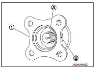
A. Oil seal lip B. Gear carrier mounting face
 : Always replace after every
disassembly.
 : Select with proper thickness.
 : N·m (kg-m, ft-lb)
 : Apply gear oil.
 : Apply anti-corrosive oil.
 : Apply multi purpose grease
 : Apply Genuine Liquid Gasket 1217
or equivalent.
Disassembly
1. Remove electric controlled coupling. Refer to DLN-147, "Disassembly".
2. Remove center stem assembly. Refer to DLN-152, "Disassembly".
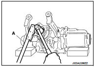
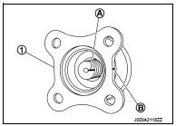
3. Remove drive pinion lock nut with the flange wrench (A) (commercial service tool).
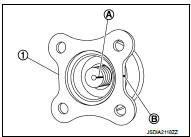
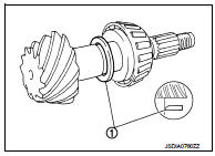
4. Put matching mark (B) on the end of drive pinion. The matching mark should be in line with the matching mark (A) on companion flange (1).
CAUTION:
For matching mark, use paint. Never damage companion
flange and drive pinion.
NOTE:
The matching mark on the final drive companion flange indicates the maximum vertical runout position.
When replacing companion flange, matching mark is not necessary.
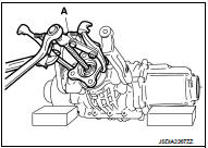
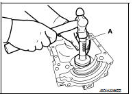
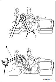
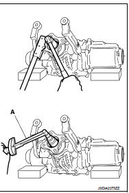
5. Remove companion flange using the pullers (A) (commercial service tool).
6. Press drive pinion assembly out of gear carrier.
CAUTION:
Never drop drive pinion assembly.
7. Remove front oil seal.
8. Remove pinion front bearing inner race.
9. Remove collapsible spacer.
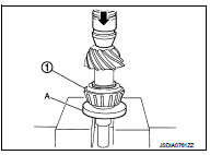
10. Remove pinion rear bearing inner race and pinion height adjusting washer with the replacer (A) (commercial service tool).
11. Remove pinion height adjusting washer.
12. Tap pinion front/rear bearing outer races uniformly using a brass rod or equivalent to remove them.
CAUTION:
Never damage gear carrier.
13. Perform inspection after disassembly. Refer to DLN-165, "Inspection".
Assembly
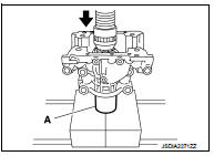
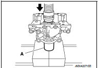
1. Install pinion front bearing outer race to the gear carrier with drift (A) (SST: ST17130000).
CAUTION:
• At first, using a hammer, tap bearing outer race until it
becomes flat to gear carrier.
• Never reuse pinion front and rear bearing outer race.
2. Install pinion rear bearing outer race to the gear carrier with drift (A) (SST: KV38100300).
CAUTION:
• At first, using a hammer, tap bearing outer race until it
becomes flat to gear carrier.
• Never reuse pinion front and rear bearing outer race.
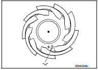
3. Temporarily install pinion height adjusting washer (1).
When hypoid gear set has been replaced • Select pinion height adjusting washer. Refer to DLN-164, "Adjustment".
When hypoid gear set has been reused • Temporarily install the removed pinion height adjusting washer or same thickness washer to drive pinion.
CAUTION:
Pay attention to the direction of pinion height adjusting
washer. (Assemble as shown in the figure.)
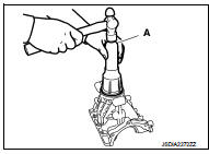
4. Install pinion rear bearing inner race (1) to drive pinion with the drift (A) (SST: ST30032000).
CAUTION:
Never reuse pinion rear bearing inner race.
5. Check and adjust the tooth contact and back lash of drive gear and drive pinion following the procedure below.
a. Assemble drive pinion into gear carrier.
CAUTION:
• Never assemble a collapsible spacer.
• Apply gear oil to pinion rear bearing.
b. Assemble pinion front bearing inner race to drive pinion assembly.
CAUTION:
• Never reuse pinion front bearing inner race.
• Apply gear oil to pinion front bearing.
c. Using drift (A) (SST: ST37710000), press the pinion front bearing inner race to drive pinion as far as drive pinion nut can be tightened.
d. Install companion flange (1).
CAUTION:
Never assemble front oil seal.
NOTE:
When reusing drive pinion, align the matching mark (B) of drive pinion with the matching mark (A) of companion flange, and then install companion flange.
e. Temporarily tighten removed drive pinion nut to drive pinion using flange wrench (commercial service tool).
NOTE
:
Use removed drive pinion nut only for the preload measurement.
f. Rotate drive pinion more than 20 times to adjust bearing.
g. Tighten to drive pinion lock nut using flange wrench (commercial service tool), while adjusting pinion bearing preload torque using preload gauge (A) (SST: ST3127S000).
Pinion bearing preload (without oil seal) : 1.0 - 1.3 N·m (0.11 – 0.13 kg-m, 9 – 11 in-lb)
CAUTION:
Drive pinion lock nut is tightened with no collapsible
spacer. Be careful not to overtighten it. While measuring the
preload, tighten it by 5° to 10°.
h. Assemble removed drive side bearing adjusting washer or same thickness of it and install center stem assembly. Refer to DLN- 153, "Assembly".
CAUTION:
Apply differential gear oil to the side bearings.
i. Check and adjust tooth contact, drive gear to drive pinion backlash. Refer to DLN-154, "Adjustment".
j. Remove center stem assembly.
k. Remove companion flange.
l. Remove drive pinion assembly from gear carrier.
m. Remove pinion front bearing inner race.
6. Assemble collapsible spacer.
CAUTION:
Never reuse collapsible spacer.
7. Assemble drive pinion into gear carrier.
CAUTION:
Apply gear oil to pinion rear bearing.
8. Assemble pinion front bearing inner race to drive pinion assembly.
CAUTION:
• Never reuse pinion front bearing inner race.
• Apply gear oil to pinion front bearing.
9. Using drift (A) (SST: ST37710000), press the pinion front bearing inner race to drive pinion as far as drive pinion nut can be tightened.
10. Install front oil seal as shown in figure with the drift (A) (commercial service tool).
CAUTION:
• Never reuse oil seal.
• When installing, never incline oil seal.
• Apply multi-purpose grease onto oil seal lips, and gear oil onto the circumference of oil seal.
11. Install companion flange (1).
NOTE
:
When reusing drive pinion, align the matching mark (B) of drive
pinion with the matching mark (A) of companion flange, and then
install companion flange.
12. Apply anti-corrosion oil to the thread and seat of drive pinion lock nut, and temporarily tighten drive pinion lock nut to drive pinion, using flange wrench (commercial service tool).
CAUTION
:
Never reuse drive pinion lock nut.
13. Adjust to the drive pinion lock nut tightening torque and pinion bearing preload torque, using preload gauge (A) (SST: ST3127S000)
Pinion bearing preload : Refer to DLN-167, "Preload Torque".
CAUTION:
• Adjust to the lower limit of the drive pinion lock nut tightening
torque first.
• If the preload torque exceeds the specified value, replace collapsible spacer and tighten it again to adjust. Never loosen drive pinion lock nut to adjust the preload torque.
• After adjustment, rotate drive pinion back and forth 2 to 3 times to check for unusual noise, rotation malfunction, and other malfunctions.
14. Install center stem assembly. Refer to DLN-153, "Assembly".
CAUTION:
Never install rear cover at this timing.
15. Check and adjust drive gear runout, tooth contact, drive gear to drive pinion backlash, and companion flange runout. Refer to DLN-154, "Adjustment" and DLN-164, "Adjustment".
16. Check total preload torque. Refer to DLN-154, "Adjustment".
17. Install rear cover. Refer to DLN-153, "Assembly".
Adjustment
PINION GEAR HEIGHT
If the hypoid gear set has been replaced, select the pinion height adjusting washer.
1. Use the formula below to calculate pinion height adjusting washer thickness.
Washer selection equation:
T = T0 + (t1− t2)
T: Correct washer thickness
T0: Removed washer thickness
t1: Old drive pinion head letter “H × 0.01”
(“H”: machined tolerance 1/100 mm × 100)
t2: New drive pinion head letter “H × 0.01”
(“H”: machined tolerance 1/100 mm × 100)
Example:
T = 3.21 + [(2 × 0.01) − (−1 × 0.01)] = 3.24
T0: 3.21
t1: +2
t2: −1
2. Select the proper pinion height adjusting washer. For selecting adjusting washer, refer to the latest parts information.
CAUTION:
If unable to find a washer of desired thickness, use a washer with thickness
closest to the calculated
value.
Example:
Calculated value... T = 3.22 mm
Used washer... T = 3.21 mm
COMPANION FLANGE RUNOUT
1. Fit a dial indicator onto the companion flange face (inner side of the rear propeller shaft mounting bolt holes).
2. Rotate companion flange to check for runout.
Companion flange runout : Refer to DLN-167, "Companion Flange Runout".
3. Fit a test indicator to the inner side of companion flange (socket diameter).
4. Rotate companion flange to check for runout.
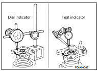
Companion flange runout : Refer to DLN-167, "Companion Flange Runout".
5. If the runout value is outside the runout limit, follow the procedure below to adjust.
a. Check for runout while changing the phase between companion flange and drive pinion by 90° step, and search for the position where the runout is the minimum.
b. If the runout value is still outside of the limit after the phase has been changed, replace companion flange.
c. If the runout value is still outside of the limit after companion flange has been replaced, possible cause will be an assembly malfunction of drive pinion and electric controlled coupling, malfunctioning coupling bearing, or malfunctioning of electric controlled coupling.
Inspection
INSPECTION AFTER DISASSEMBLY
Drive Gear and Drive Pinion • Clean up the disassembled parts.
• If the gear teeth never mesh or line-up correctly, determine the cause and adjust or replace as necessary.
• If the gears are worn, cracked, damaged, pitted or chipped (by friction) noticeably, replace with new drive gear and drive pinion as a set.
Bearing
• Clean up the disassembled parts.
• If any chipped (by friction), pitted, worn, rusted or scratched marks, or unusual noise from the bearing is observed, replace as a bearing assembly (as a new set).
Oil Seal
• Whenever disassembled, replace.
• If wear, deterioration of adherence (sealing force lips), or damage is detected on the lips, replace them.
Companion Flange
• Clean up the disassembled parts.
• If any chipped mark [about 0.1 mm, (0.004 in)] or other damage on the contact sides of the lips of the companion flange is found, replace.
 Center stem assembly
Exploded View
1. Filler plug
2. Gasket
3. Drain plug
4. Breather tube
5. Clip
6. Breather hose
7. Breather
8. sub-harness clip
9. sub-harness
10. Rear cover
11. Center stem
12. Si ...

Other materials:
C1101, C1102, C1103, C1104 WHEEL SENSOR
DTC Logic
DTC DETECTION LOGIC
DTC CONFIRMATION PROCEDURE
1.PRECONDITIONING
If “DTC CONFIRMATION PROCEDURE” has been previously conducted, always turn
ignition switch OFF and
wait at least 10 seconds before conducting the next test.
>> GO TO 2.
2.CHECK DTC DETECTION
With CON ...
Unit removal and installation
Transaxle assembly
Exploded View
1. CVT fluid level gauge
2. CVT fluid charging pipe
3. O-ring
4. Transaxle assembly
5. Air breather hose
A. For tightening torque, refer to TM-301, "Removal and Installation".
Removal and Intallation
REMOVAL
WARNING:
Never remove the reservo ...
Clutch piping
Exploded View
RS5F92R
1. CSC (Concentric Slave Cylinder)
2. Clutch tube
3. Clutch damper
4. Bracket
5. Master cylinder
RS6F94R
1. CSC (Concentric Slave Cylinder)
2. Clutch tube
3. Clutch damper
4. Bracket
5. Master cylinder
Hydraulic Layout
1. Clutch tube
2. Lock pin
3. ...
