Nissan Juke Service and Repair Manual : System
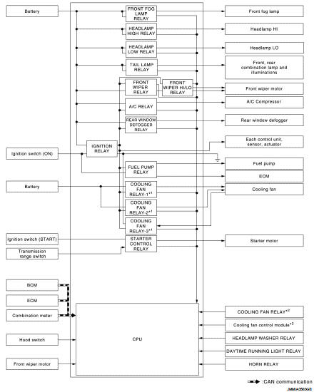
Relay control system
RELAY CONTROL SYSTEM : System Diagram
*1: Except for MR16DDT engine models *2: For MR16DDT engine models
RELAY CONTROL SYSTEM : System Description
IPDM E/R activates the internal control circuit to perform the relay ON-OFF control according to the input signals from various sensors and the request signals received from control units via CAN communication.
CAUTION:
IPDM E/R integrated relays cannot be removed.
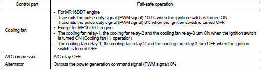
RELAY CONTROL SYSTEM : Fail-Safe
CAN COMMUNICATION CONTROL
When CAN communication with ECM and BCM is impossible, IPDM E/R performs fail-safe control. After CAN communication recovers normally, it also returns to normal control.
If No CAN Communication Is Available With ECM
If No CAN Communication Is Available With BCM
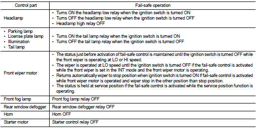
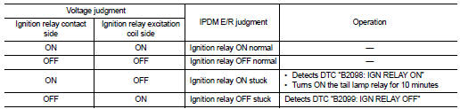
IGNITION RELAY MALFUNCTION DETECTION FUNCTION
• IPDM E/R monitors the voltage at the contact circuit and excitation coil circuit of the ignition relay inside it.
• IPDM E/R judges the ignition relay error if the voltage differs between the contact circuit and the excitation coil circuit.
• If the ignition relay cannot turn OFF due to contact seizure, it activates the tail lamp relay for 10 minutes to alert the user to the ignition relay malfunction when the ignition switch is turned OFF.
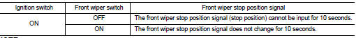
FRONT WIPER PROTECTION FUNCTION
IPDM E/R detects front wiper stop position by a front wiper stop position signal.
When a front wiper stop position signal is in the conditions listed below, IPDM E/R stops power supply to wiper after repeating a front wiper 10 seconds activation and 20 seconds stop.
NOTE
:
This operation status can be confirmed on the IPDM E/R “Data Monitor” that
displays “BLOCK” for the item
“WIP PROT” while the wiper is stopped.
STARTER MOTOR PROTECTION FUNCTION
IPDM E/R turns OFF the starter control relay to protect the starter motor when the starter control relay remains active for 90 seconds.
Power control system
POWER CONTROL SYSTEM : System Diagram
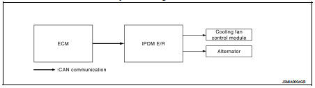
POWER CONTROL SYSTEM : System Description
COOLING FAN CONTROL (ONLY FOR MODELS WITH MR16DDT ENGINE)
IPDM E/R outputs pulse duty signal (PWM signal) to the cooling fan control module according to the status of the cooling fan speed request signal received from ECM via CAN communication. Refer to EC-61, "COOLING FAN CONTROL : System Diagram".
NOTE
:
After ignition switch OFF, IPDM E/R turn the cooling fan relay ON and outputs
pulse duty signal (PWM signal)
to the cooling fan control module according to the request signal from ECM for
cooling the engine according to
the situation.
ALTERNATOR CONTROL
IPDM E/R outputs power generation command signal (PWM signal) to the alternator according to the status of the power generation command value signal received from ECM via CAN communication. Refer to CHG-9, "POWER GENERATION VOLTAGE VARIABLE CONTROL SYSTEM : System Diagram (Gasoline Engine Models)".
Signal buffer system
SIGNAL BUFFER SYSTEM : System Diagram
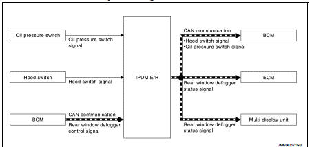
SIGNAL BUFFER SYSTEM : System Description
• NOTE
:
Only for K9K engine models
IPDM E/R reads the status of the oil pressure switch and transmits the oil
pressure switch signal to BCM via
CAN communication. Refer to MWI-12, "OIL PRESSURE WARNING LAMP : System
Diagram".
• IPDM E/R reads the status of the hood switch and transmits the hood switch signal to BCM via CAN communication.
Refer to SEC-174, "VEHICLE SECURITY SYSTEM : System Diagram".
• IPDM E/R receives the rear window defogger control signal from BCM via CAN communication and transmits the rear window defogger status signal to ECM and multi display unit via CAN communication. Refer to DEF-7, "WITH AUTO A/C : System Diagram" (with AUTO A/C) or DEF-7, "WITHOUT AUTO A/C : System Diagram" (without AUTO A/C).
Power consumption control system
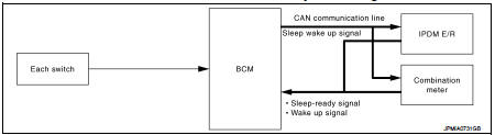
POWER CONSUMPTION CONTROL SYSTEM : System Diagram
POWER CONSUMPTION CONTROL SYSTEM : System Description
OUTLINE
• IPDM E/R incorporates a power consumption control function that reduces the power consumption according to the vehicle status.
• IPDM E/R changes its status (control mode) with the sleep wake up signal received from BCM via CAN communication.
Normal mode (wake-up)
- CAN communication is normally performed with other control units.
- Individual unit control by IPDM E/R is normally performed.
Low power consumption mode (sleep) - Low power consumption control is active.
- CAN transmission is stopped.
SLEEP MODE ACTIVATION
• IPDM E/R judges that the sleep-ready conditions are fulfilled when the ignition switch is OFF and none of the conditions below are present. Then it transmits a sleep-ready signal (ready) to BCM via CAN communication.
- Outputting signals to actuators - Switches or relays operating - Output requests are being received from control units via CAN communication.
• IPDM E/R stops CAN communication and enters the low power consumption mode when it receives a sleep wake up signal (sleep) from BCM and the sleep-ready conditions are fulfilled.
WAKE-UP OPERATION
• IPDM E/R changes from the low power consumption mode to the normal mode when
it receives a sleep
wake-up signal (wake up) from BCM or any of the following conditions is
fulfilled. In addition, it transmits a
sleep-ready signal (not-ready) to BCM via CAN communication to report the CAN
communication start.
- Ignition switch ON
- An output request is received from a control unit via CAN communication.
 Component parts
Component Parts Location
1. IPDM E/R
A. Engine room (LH) ...
 Diagnosis system (IPDM E/R)
Diagnosis Description
AUTO ACTIVE TEST
Description
In auto active test mode, the IPDM E/R sends a drive signal to the following
systems to check their operation.
• Oil pressure warning lamp ...
Other materials:
Hazard warning flasher switch
Push the switch on to warn other drivers when you must stop or park under emergency
conditions.
All turn signal lights will flash.
WARNING
• If stopping for an emergency, be sure to move the vehicle well off
the road.
• Do not use the hazard warning flashers while moving on ...
Draining
1. Start engine and let it run to warm up transaxle.
2. Stop engine. Remove drain plug (1) and gasket, using a socket
[Commercial service tool] and then drain gear oil.
3. Set a gasket on drain plug and install it to clutch housing, using
a socket [Commercial service tool].
CAUTION:
Never re ...
Engine emits blue smoke
Description
CHART 19: ENGINE EMITS BLUE SMOKE
Diagnosis Procedure
1.CHECK ENGINE OIL
Check the grade of engine oil. Refer to LU-33, "Inspection".
Is the inspection result normal?
YES >> GO TO 2.
NO >> Replace engine oil. Refer to LU-34, "Refilling".
2.CH ...
