Nissan Juke Service and Repair Manual : Additional service when replacing transaxle assembly
Description
Perform the following work after the transaxle assembly is replaced.
Erasing the calibration data • The TCM acquires calibration data (individual characteristic value) of each solenoid that is stored in the ROM assembly (in the control valve). This enables the TCM to perform accurate control. For this reason, after the transaxle assembly is replaced, it is necessary to erase the calibration data that is stored in the TCM and load new calibration data.
Erasing the learned value data • TCM learns indicated pressure for appropriate control of the transaxle assembly and records the learned values. For this reason, the leaned values stored in TCM must be erased after replacing a transaxle assembly.
Erasing CVT fluid degradation level data • TCM records the degradation level of the CVT fluid calculated from the vehicle driving status. Therefore, if the transaxle assembly is replaced, it is necessary to erase the CVT fluid degradation level data recorded by TCM.
Procedure
1.INITIALIZE TCM
 With CONSULT-III
1. Set parking brake.
2. Turn ignition switch ON.
3. Select “Work Support” in “TRANSMISSION”.
4. Select “ERASE MEMORY DATA”.
5. While maintaining the conditions below, touch “Start”.
- Vehicle stop status
- With engine stopped
- Selector lever: “R” position
- Accelerator pedal: Depressed
NOTE
:
Select “Start” and complete within approximately 20 seconds.
Is “COMPLETED” displayed? YES >> GO TO 2.
NO >> Turn the ignition switch OFF and wait for a minimum of 10 seconds then perform the work again.
2.CHECK AFTER TCM IS INITIALIZED
 With CONSULT-III
1. Turn ignition switch OFF with the selector lever in “R” position and wait for 10 seconds or more.
2. Turn ignition switch ON with the selector lever in “R” position.
CAUTION:
Never start the engine.
3. Select “Special function” in “TRANSMISSION”.
4. Select “CALIB DATA”.
5. Check that indicated value of “CALIB DATA” is equal to the value shown in the following table.
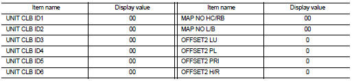
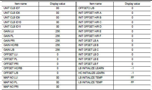
Is the indicated value of “CALIB DATA” equal to the value shown in the table? YES >> GO TO 3.
NO >> GO TO 1.
3.LOADING OF CALIBRATION DATA
1. Shift the selector lever to the “P” position.
2. Check that “P” is displayed on shift position indicator on combination meter.
NOTE
:
Displayed approximately 4 – 5 seconds after the selector lever is moved to the
“P” position.
Does shift position indicator display “P”? YES >> GO TO 5.
NO >> GO TO 4.
4.DETECTION OF MALFUNCTION ITEMS
Check the following items: • Harness between the TCM and the ROM assembly inside the transaxle assembly is open or shorted.
• Disconnected, loose, bent, collapsed, or otherwise abnormal connector housing terminals Is the inspection result normal? YES >> GO TO 1.
NO >> Repair or replace the malfunctioning parts.
5.ERASE THE CVT FLUID DEGRADATION LEVEL DATA
 With CONSULT-III
1. Select “WORK SUPPORT” in “TRANSMISSION”.
2. Select “CONFORM CVTF DETERIORTN”.
3. Touch “Clear”.
>> WORK END
 Additional service when replacing TCM
Description
Always perform the following items when the TCM is replaced.
CHECK LOADING OF CALIBRATION DATA
• The TCM acquires calibration data (individual characteristic value) of each
soleno ...
 G sensor calibration
Description
TCM stores calibration data (inherent characteristic value) of G sensor to
provide accurate control. Therefore,
it is required to perform calibration of G sensor after the following wo ...
Other materials:
Front disc brake
Brake pad : Inspection and Adjustment
INSPECTION
Check brake pad wear thickness from an inspection hole on cylinder
body. Check using a scale if necessary.
Wear thickness : Refer to BR-71, "Front Disc Brake".
ADJUSTMENT
Burnish contact surfaces between disc rotor and brake pads acc ...
Water hose
Exploded View
1. Hose clamp
2. Water hose
A. Water outlet
B. Oil warm
Removal and Installation
REMOVAL
WARNING:
Never remove the radiator cap when the engine is hot. Serious burns could occur
from high pressure
coolant escaping from the radiator.
CAUTION:
Perform these steps after t ...
Vehicle speed sensing auto lock operation does not operate
Diagnosis Procedure
1.CHECK “AUTOMATIC LOCK/UNLOCK SELECT” SETTING IN “WORK SUPPORT”
1. Select “DOOR LOCK” of “BCM” using CONSULT-III.
2. Select “AUTOMATIC LOCK/UNLOCK SELECT” in “WORK SUPPORT” mode.
3. Check “AUTOMATIC LOCK/UNLOCK SELECT” setting in “WORK SUPPORT†...
