Nissan Juke Service and Repair Manual : Blower fan on signal
Component Function Check
1.CHECK BLOWER FAN ON SIGNAL
 With CONSULT-III
1. Turn ignition switch ON.
2. Select “AIR CONDITIONER” of “BCM” using CONSULT-III.
3. Select “FAN ON SIG” in “DATA MONITOR” mode.
4. Check blower fan ON signal when the fan switch is operated.
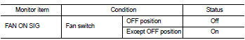
Is the inspection result normal? YES >> INSPECTION END
NO >> Refer to HAC-168, "Diagnosis Procedure".
Diagnosis Procedure
1.CHECK BLOWER FAN ON SIGNAL
1. Turn ignition switch OFF.
2. Disconnect A/C auto amp. harness connector.
3. Turn ignition switch ON.
4. Check output waveform between A/C auto amp. and ground with using oscilloscope.
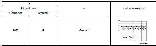
Is the inspection result normal? YES >> Replace A/C auto amp. Refer to HAC-188, "Removal and Installation".
NO >> GO TO 2.
2.CHECK BLOWER FAN ON SIGNAL CIRCUIT FOR OPEN
1. Turn ignition switch OFF.
2. Disconnect BCM connector.
3. Check continuity A/C auto amp. harness connector and BCM harness connector.
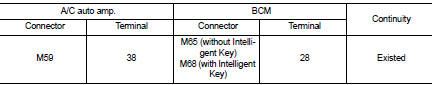
Is the inspection result normal? YES >> GO TO 3.
NO >> Repair harness or connector.
3.CHECK BLOWER FAN ON SIGNAL CIRCUIT FOR SHORT
Check continuity between A/C auto amp. harness connector and ground.
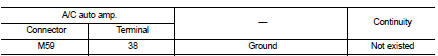
Is the inspection result normal? YES >> Replace BCM. Refer to BCS-93, "Removal and Installation" (with Intelligent Key) or BCS-161, "Removal and Installation" (without Intelligent Key).
NO >> Repair harness or connector.
 A/C on signal
Component Function Check
1.CHECK A/C ON SIGNAL
With CONSULT-III
1. Turn ignition switch ON.
2. Operate blower motor.
3. Select “AIR CONDITIONER” of “BCM” using CONSULT-III.
4. Select “ ...
 Blower motor
Diagnosis Procedure
1.CHECK SYMPTOM
Check symptom (A, B or C).
Which symptom is detected?
A >>GO TO 2.
B >>GO TO 11.
C >> GO TO 13.
2.CHECK FUSE
1. Turn ignition switch O ...
Other materials:
Additional service when removing battery negative terminal
Description
• The audio unit is equipped with the anti-theft system.
• The audio unit operates after authenticating a fixed four-digit anti-theft
code.
• After removing the battery of the audio unit, the authentication of the
anti-theft code is required.
Work Procedure
1.POWER SWITCH ...
Recommended fluids and lubricants
Fluids and Lubricants
*1: For additional information, see “SAE Viscosity Number”.
*2: Use Genuine NISSAN Engine Coolant or equivalent in its quality, in order to
avoid possible aluminium corrosion within the engine
cooling system caused by the use of non-genuine engine coolant. Note that ...
Rear door
Exploded View
1. Rear door panel
2. Door hinge (upper)
3. Door hinge (lower)
4. Door check link
5. Door striker
6. TORX bolt
: Do not reuse
: NВ·m (kg-m, in-lb)
NВ·m (kg-m, ft-lb)
: Body grease
Door assembly
DOOR ASSEMBLY : Removal and Installation
CAUTION:
• Perform work with ...
