Nissan Juke Service and Repair Manual : Blower motor
Diagnosis Procedure
1.CHECK SYMPTOM
Check symptom (A, B or C).
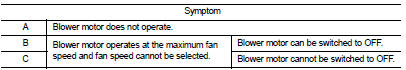
Which symptom is detected? A >>GO TO 2.
B >>GO TO 11.
C >> GO TO 13.
2.CHECK FUSE
1. Turn ignition switch OFF.
2. Check following fuses.
- 10A fuse [No. 15, located in fuse block (J/B)] - 15A fuses [Nos. 14 and 16, located in the fuse block (J/B)]
NOTE
:
Refer to PG-22, "Fuse, Connector and Terminal Arrangement".
Is the inspection result normal? YES >> GO TO 3.
NO >> Replace the blown fuse after repairing the affected circuit if a fuse is blown.
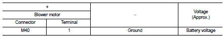
3.CHECK BLOWER MOTOR POWER SUPPLY
1. Disconnect blower motor connector.
2. Turn ignition switch ON.
3. Check voltage between blower motor harness connector and ground.
Is the inspection result normal? YES >> GO TO 5.
NO >> GO TO 4.
4.CHECK BLOWER RELAY
1. Turn ignition switch OFF.
2. Check blower relay. Refer to HAC-173, "Component Inspection (Blower Relay)".
Is the inspection result normal? YES >> Repair harness or connector between blower motor and fuse.
NO >> Replace blower relay.
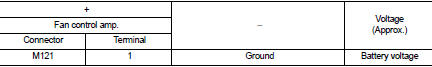
5.CHECK FAN CONTROL AMP. POWER SUPPLY (SOURCE) CIRCUIT
1. Turn ignition switch OFF.
2. Connect blower motor connector.
3. Disconnect fan control amp. connector.
4. Turn ignition switch ON.
5. Check voltage between fan control amp. harness connector and ground.
Is the inspection result normal? YES >> GO TO 7.
NO >> GO TO 6.
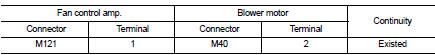
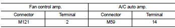
6.CHECK FAN CONTROL AMP. POWER SUPPLY (SOURCE) CIRCUIT FOR OPEN
1. Turn ignition switch OFF.
2. Disconnect blower motor connector.
3. Check continuity between fan control amp. harness connector and blower motor harness connector.
Is the inspection result normal? YES >> Replace blower motor. Refer to VTL-15, "Removal and Installation (LHD models)" or VTL-16, "Removal and Installation (RHD models)".
NO >> Repair harness or connector.
7.CHECK FAN CONTROL AMP. GROUND (DRAIN) CIRCUIT FOR OPEN
1. Turn ignition switch OFF.
2. Check continuity between fan control amp. harness connector and ground.
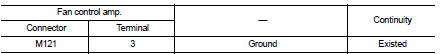
Is the inspection result normal? YES >> GO TO 8.
NO >> Repair harness or connector.
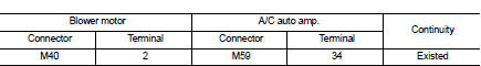
8.CHECK FAN CONTROL AMP. CONTROL SIGNAL (GATE) CIRCUIT FOR OPEN
1. Disconnect A/C auto amp. connector.
2. Check continuity between fan control amp. harness connector and A/C auto amp. harness connector.
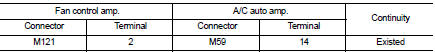
Is the inspection result normal? YES >> GO TO 9.
NO >> Repair harness or connector.
9.CHECK FAN CONTROL AMP. CONTROL SIGNAL (GATE) CIRCUIT FOR SHORT
Check continuity between fan control amp. harness connector and ground.
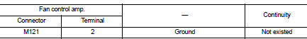
Is the inspection result normal? YES >> GO TO 10.
NO >> Repair harness or connector.
10.CHECK FAN CONTROL AMP.
Check fan control amp. Refer to HAC-173, "Component Inspection (Fan Control Amp.)".
Is the inspection result normal? YES >> Replace A/C auto amp. Refer to HAC-188, "Removal and Installation".
NO >> Replace fan control amp. Refer to HAC-194, "Removal and Installation".
11.CHECK A/C AUTO AMP. IGNITION POWER SUPPLY FEEDBACK SIGNAL
1. Turn ignition switch ON.
2. Check voltage between A/C auto amp. harness connector and ground.
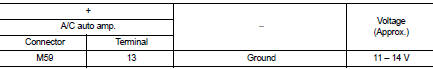
Is the inspection result normal? YES >> GO TO 12.
NO >> Repair harness or connector between A/C auto amp. and fuse.
12.CHECK BLOWER MOTOR FEEDBACK SIGNAL CIRCUIT FOR OPEN
1. Turn ignition switch OFF.
2. Disconnect blower motor connector and A/C auto amp. connector.
3. Check continuity between blower motor harness connector and A/C auto amp. harness connector.
Is the inspection result normal? YES >> Replace A/C auto amp. Refer to HAC-188, "Removal and Installation".
NO >> Repair harness or connector.
13.CHECK BLOWER MOTOR FEEDBACK SIGNAL CIRCUIT AND FAN CONTROL AMP. POWER SUPPLY (SOURCE) CIRCUIT FOR SHORT
1. Turn ignition switch OFF.
2. Disconnect following connectors.
- Blower fan motor
- Fan control amp.
- A/C auto amp.
3. Check continuity between blower motor harness connector and ground.
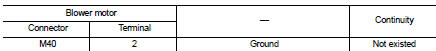
Is the inspection result normal? YES >> GO TO 14.
NO >> Repair harness or connector.
14.CHECK FAN CONTROL AMP. CONTROL SIGNAL (GATE) CIRCUIT FOR SHORT TO POWER SUPPLY
Check harness between fan control amp. harness connector and A/C auto amp. harness connector for short to power supply.
Is the inspection result normal? YES >> GO TO 10.
NO >> Repair harness or connector.
Component Inspection (Blower Motor)
1.CHECK BLOWER MOTOR
1. Remove blower motor. Refer to VTL-15, "Removal and Installation (LHD models)" or VTL-16, "Removal and Installation (RHD models)".
2. Check that there is not any mixing foreign object in the blower motor.
Is the inspection result normal? YES >> GO TO 2.
NO >> Replace blower motor. Refer to VTL-15, "Removal and Installation (LHD models)" or VTL-16, "Removal and Installation (RHD models)".
2.CHECK BLOWER MOTOR
Check that there is not breakage or damage in the blower motor.
Is the inspection result normal? YES >> GO TO 3.
NO >> Replace blower motor. Refer to VTL-15, "Removal and Installation (LHD models)" or VTL-16, "Removal and Installation (RHD models)".
3.CHECK BLOWER MOTOR
Check that blower motor turns smoothly.
Is the inspection result normal? YES >> INSPECTION END
NO >> Replace blower motor. Refer to VTL-15, "Removal and Installation (LHD models)" or VTL-16, "Removal and Installation (RHD models)".
Component Inspection (Blower Relay)
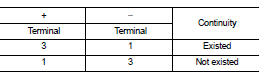
1.CHECK BLOWER RELAY
1. Remove blower relay. Refer to PG-22, "Fuse, Connector and Terminal Arrangement".
2. Check continuity between blower relay terminal 3 and 5 when the voltage is supplied between terminal 1 and 2.
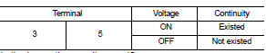
Is the inspection result normal? YES >> INSPECTION END
NO >> Replace blower relay.
Component Inspection (Fan Control Amp.)
1.CHECK FAN CONTROL AMP.
1. Remove fan control amp. Refer to HAC-194, "Removal and Installation".
2. Check continuity between fan control amp. terminals.
Is the inspection result normal? YES >> INSPECTION END
NO >> Replace fan control amp. Refer to HAC-194, "Removal and Installation".
 Blower fan on signal
Component Function Check
1.CHECK BLOWER FAN ON SIGNAL
With CONSULT-III
1. Turn ignition switch ON.
2. Select ŌĆ£AIR CONDITIONERŌĆØ of ŌĆ£BCMŌĆØ using CONSULT-III.
3. Select ŌĆ£FAN ON SIGŌĆØ in ŌĆ ...
 Magnet clutch
Component Function Check
1.CHECK MAGNET CLUTCH OPERATION
Perform auto active test of IPDM E/R. Refer to PCS-12, "Diagnosis
Description" (with Intelligent Key) or PCS-
43, "Diagnosi ...
Other materials:
Basic inspection
DIAGNOSIS AND REPAIR WORKFLOW
Work Flow
OVERALL SEQUENCE
DETAILED FLOW
1.INTERVIEW FOR MALFUNCTION
Interview the symptom to the customer.
>> GO TO 2.
2.SYMPTOM CHECK
Check the symptom from the customer's information.
>> GO TO 3.
3.BASIC INSPECTION
Check the operation o ...
Install
1. Align the head restraint/headrest stalks with the holes in the seat. Make
sure that the head restraint/headrest is facing the correct direction. The stalk
with the adjustment notch1 must be installed in the hole with the lock knob2 .
2. Push and hold the lock knob and push the head restrai ...
Inspection
INSPECTION AFTER REMOVAL
Check the following items, and replace the part if necessary.
ŌĆó Move joint up/down, left/right, and in the axial directions. Check for motion
that is not smooth and for significant
looseness.
ŌĆó Check boot for cracks, damage, and leakage of grease.
ŌĆó Check the ...
