Nissan Juke Service and Repair Manual : Magnet clutch
Component Function Check
1.CHECK MAGNET CLUTCH OPERATION
Perform auto active test of IPDM E/R. Refer to PCS-12, "Diagnosis Description" (with Intelligent Key) or PCS- 43, "Diagnosis Description" (without Intelligent Key).
Does it operate normally? YES >> INSPECTION END
NO >> Refer to HAC-175, "Diagnosis Procedure".
Diagnosis Procedure
1.CHECK FUSE
1. Turn ignition switch OFF.
2. Check 10A fuse (No. 49, located in IPDM E/R).
NOTE
:
Refer to PG-25, "Fuse, Connector and Terminal Arrangement".
Is the inspection result normal? YES >> GO TO 2.
NO >> Replace the blown fuse after repairing the affected circuit if a fuse is blown.
2.CHECK MAGNET CLUTCH
1. Disconnect compressor connector.
2. Directly apply battery voltage to the magnet clutch. Check for operation visually and by sound.
Does it operate normally? YES >> GO TO 3.
NO-1 >> HR16DE: Replace magnet clutch. Refer to HA-32, "MAGNET CLUTCH : Removal and Installation of Compressor Clutch".
NO-2 >> MR16DDT: Replace magnet clutch. Refer to HA-88, "MAGNET CLUTCH : Removal and Installation of Compressor Clutch".
NO-3 >> K9K: Replace magnet clutch.
3.CHECK MAGNET CLUTCH POWER SUPPLY CIRCUIT FOR OPEN
1. Disconnect IPDM E/R connector.
2. Check continuity between IPDM E/R harness connector and compressor harness connector.
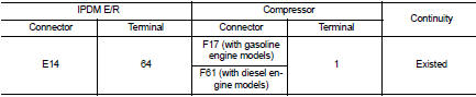
Is the inspection result normal? YES >> Replace IPDM E/R. Refer to PCS-34, "Removal and Installation" (with Intelligent Key) or PCS-63, "Removal and Installation" (without Intelligent Key).
NO >> Repair harness or connector.
 Blower motor
Diagnosis Procedure
1.CHECK SYMPTOM
Check symptom (A, B or C).
Which symptom is detected?
A >>GO TO 2.
B >>GO TO 11.
C >> GO TO 13.
2.CHECK FUSE
1. Turn ignition switch O ...
 PTC heater
Component Function Check
1.CHECK PTC HEATER OPERATION
1. Start the engine.
2. Operate fan control dial.
3. Operate temperature control dial to full hot position.
4. Check for warm air at discharg ...
Other materials:
Engine idle speed too low or unstable
Description
CHART 6: ENGINE IDLE SPEED TOO LOW OR UNSTABLE
Diagnosis Procedure
1.CHECK FUEL
Check that the fuel reservoir is correctly filled and with the right fuel.
>> GO TO 2.
2.CHECK ECM POWER SUPPLY AND GROUND CIRCUIT
Check ECM power supply and ground circuit. Refer to EC-885, ...
The seat belt reminder warning continues sounding, or
does not sound
Description
ŌĆó Seat belt reminder warning does not sound.
ŌĆó Seat belt reminder warning sounds continuously.
Diagnosis Procedure
1.CHECK SEAT BELT WARNING LAMP
1. Turn ignition switch ON.
2. Check the operation of the seat belt warning lamp in the combination meter.
Seat belt (driver side) ...
B1215, B1216, B1217 satellite sensor LH
DTC Logic
DTC DETECTION LOGIC
DTC CONFIRMATION PROCEDURE
1.CHECK SELF-DIAG RESULT
With CONSULT-III
1. Turn ignition switch ON.
2. Perform ŌĆ£Self Diagnostic ResultŌĆØ mode of ŌĆ£AIR BAGŌĆØ using CONSULT-III.
Without CONSULT-III
1. Turn ignition switch ON.
2. Check the air bag warning la ...
