Nissan Juke Service and Repair Manual : System
POWER DISTRIBUTION SYSTEM
POWER DISTRIBUTION SYSTEM : System Description
SYSTEM DESCRIPTION
• PDS (POWER DISTRIBUTION SYSTEM) is the system that BCM controls with the operation of the pushbutton ignition switch and performs the power distribution to each power circuit. This system is used instead of the mechanical power supply changing mechanism with the operation of the conventional key cylinder.
• The push-button ignition switch can be operated when Intelligent Key is in the following condition. Refer to Engine Start Function for details.
- Intelligent Key is in the detection area of the interior antenna.
- Intelligent Key backside is contacted to push-button ignition switch.
• The push-button ignition switch operation is input to BCM as a signal. BCM changes the power supply position according to the status and operates the following relays to supply power to each power circuit.
- Ignition relay (IPDM E/R)
- Ignition relay (fuse block)
- ACC relay
- Blower fan relay
NOTE
:
The engine switch operation changes due to the conditions of brake pedal,
selector lever and vehicle speed.
• The power supply position can be confirmed with the lighting of ACC/ON indicator in the push-button ignition switch.
BATTERY SAVER SYSTEM
When all the following conditions are met for 60 minutes, the battery saver system will cut off the power supply to prevent battery discharge.
• The ignition switch is in the ACC position
• All doors are closed
• Selector lever is in the P position
Reset Condition of Battery Saver System
CVT models
In order to prevent the battery from discharging, the battery saver system will
cut off the power supply when all
doors are closed, the selector lever is on P position and the ignition switch is
left on ACC position for 60 minutes.
If any of the following conditions are met the battery saver system is released and the steering will change automatically to lock position from OFF position.
• Opening any door
• Operating with request switch on door lock
• Operating with Intelligent Key on door lock
Press push-button ignition switch and ignition switch will change to ACC position from OFF position.
M/T models
If any of the conditions above is met the battery saver system is released but
the steering will not lock.
In this case, the steering operation OFF to LOCK is prohibited.
STEERING LOCK OPERATION
Steering is locked by steering lock unit when ignition switch is in the OFF position, selector lever is in the P position and any of the following conditions are met.
• Opening door
• Closing door
• Door is locked with door request switch
• Door is locked with Intelligent Key
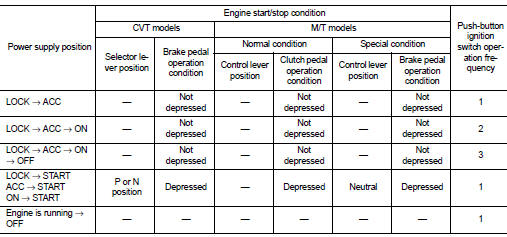
POWER SUPPLY POSITION CHANGE TABLE BY PUSH-BUTTON IGNITION SWITCH OPERATION
The power supply position changing operation can be performed with the following operations.
NOTE
:
• When an Intelligent Key is within the detection area of inside key antenna and
when Intelligent Key backside
is contacted to push-button ignition switch, it is equivalent to the operations
below.
• When starting the engine, the BCM monitors under the engine start conditions,
CVT models
- Brake pedal operating condition
- Selector lever position
- Vehicle speed
M/T models
- Clutch pedal operating condition
- Brake pedal operating condition
- Control lever position
- Vehicle speed
Vehicle speed: less than 4 km/h (2.5 MPH)
Vehicle speed: 4 km/h (2.5 MPH) or mor
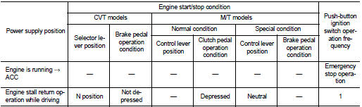
Emergency stop operation • Press and hold the push-button ignition switch for 2 seconds or more.
• Press the push-button ignition switch 3 times or more within 1.5 seconds.
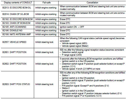
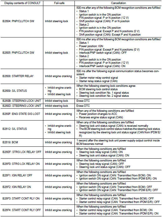
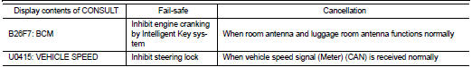
Fail-safe
FAIL-SAFE CONTROL BY DTC
BCM performs fail-safe control when any DTC are detected.
REAR WIPER MOTOR PROTECTION
BCM detects the rear wiper stopping position according to the rear wiper stop position signal.
When the rear wiper stop position signal does not change for more than 5 seconds while driving the rear wiper, BCM stops power supply to protect the rear wiper motor.
Condition of cancellation 1. More than 1 minute is passed after the rear wiper stop.
2. Turn rear wiper switch OFF.
3. Operate the rear wiper switch or rear washer switch.
FAIL-SAFE CONTROL BY LIGHT AND RAIN SENSOR MALFUNCTION
BCM detects the light and rain sensor serial link error and the light and rain sensor malfunction.
BCM controls the following fail-safe when light and rain sensor has a malfunction.
Fail-safe Control
• Auto light control: Headlamp low beam, parking lamp, license plate lamp and
tail lamp are turned ON.
• Front wiper control
- Front wiper switch AUTO and sensing rain drop: The condition just before the
activation of fail-safe is maintained
until the front wiper switch is turned OFF.
- Front wiper switch AUTO and not sensing rain drop: Front wiper is LO operation until the front wiper switch is turned off.
FAIL-SAFE CONTROL OF COMBINATION SWITCH READING FUNCTION CAUSED BY LOW POWER SUPPLY VOLTAGE
If voltage of battery power supply lower, BCM maintains combination switch reading to the status when input voltage is less than approximately 9 V.
NOTE
:
When voltage of battery power supply is approximately 9 V or more, combination
switch reading function
returns to normal operation.
 Component parts
Component Parts Location
1. Push-button ignition switch
2. Stop lamp switch
Refer to BRC-9, "Component Parts
Location" (without EPS), BRC-97,
"Component Parts Location" (wi ...
 Diagnosis system (BCM)
Common item
COMMON ITEM : CONSULT-III Function (BCM - COMMON ITEM)
APPLICATION ITEM
CONSULT-III performs the following functions via CAN communication with BCM.
SYSTEM APPLICATION
BCM can perfo ...
Other materials:
Rear window and outside mirror defroster switch
Type A (if so equipped)
To effectively clear frost, fog, or condensation from the rear window glass and the outside rearview mirrors of your Nissan Leaf, ensure the power switch is in the ON position and press the defroster switch (1) to activate the system.
...
Ignition position warning function does not operate
Diagnosis Procedure
1.CHECK DTC WITH BCM
Check that DTC is not detected with BCM.
Is the inspection result normal?
YES >> GO TO 2.
NO >> Refer to BCS-67, "DTC Index".
2.CHECK POWER DOOR LOCK OPERATION
Check power door lock operation.
Does door lock/unlock with d ...
Traction AA, A, B and C
The traction grades, from highest to lowest, are AA, A, B and C. Those grades
represent the tire’s ability to stop on wet pavement as measured under controlled
conditions on specified government test surfaces of asphalt and concrete. A tire
marked C may have poor traction performance.
WARNI ...
