Nissan Juke Service and Repair Manual : Component parts
Component Parts Location
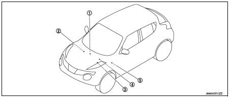
1. Push-button ignition switch
2. Stop lamp switch
Refer to BRC-9, "Component Parts
Location" (without EPS), BRC-97,
"Component Parts Location" (with
EPS)
3. IPDM E/R
Refer to PCS-5, "Component Parts
Location"
4. Transmission range switch
Refer to TM-131, "CVT CONTROL
SYSTEM : Component Parts Location"
(RE0F10B), TM-314, "CVT
CONTROL SYSTEM : Component
Parts Location" (RE0F11A)
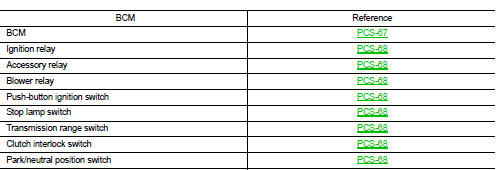
5. BCM
Refer to BCS-6, "BODY CONTROL
SYSTEM : Component Parts Location"
Component Description
BCM
BCM controls the various electrical components and simultaneously supplies power according to the power supply position.
BCM checks the power supply position internally.
Ignition Relay
BCM turns ON the following relays to supply ignition power supply or ignition switch ON signal to each ECU when the ignition switch is turned ON.
• Ignition relay (fuse block) • Ignition relay (IPDM E/R) • Blower relay
BCM compares following status comparing.
• Ignition relay (fuse block) control signal, and power supply position judged
by BCM
• Ignition relay (IPDM E/R) control request, and Ignition relay (IPDM E/R)
status
Accessory Relay
BCM turns ON the accessory relays to supply accessory power supply or ignition switch ACC signal to each ECU when the ignition switch is turned ACC or ON.
BCM compares status of accessory relay control signal, and power supply position judged by BCM.
Blower Relay
BCM turns ON the following relays to supply ignition power supply or ignition switch ON signal to each ECU when the ignition switch is turned ON.
• Ignition relay (fuse block) • Ignition relay (IPDM E/R) • Blower relay
BCM compares status of blower relay control signal, and power supply position judged by BCM.
Push-Button Ignition Switch
BCM transmits the change in the power supply position with the push-button ignition switch to IPDM E/R via CAN communication line. IPDM E/R transmits the power supply position status via CAN communication line to BCM.
Stop Lamp Switch
Stop lamp switch detects that brake pedal is depressed, and then transmits the signal to BCM.
Transmission Range Switch
Transmission range switch is integrated in CVT assembly, and detects the CVT shift selector position.
Transmission range switch detects selector lever position (P/N position), and transmits the P/N position signal to BCM and IPDM E/R.
Clutch Interlock Switch
Clutch interlock switch detects that clutch pedal is depressed, and transmits ON/OFF signal to BCM.
Park/Neutral Position Switch
Park/neutral position switch detects that control lever is in the neutral position, and then transmits neutral potision signal to BCM.

 System
POWER DISTRIBUTION SYSTEM
POWER DISTRIBUTION SYSTEM : System Description
SYSTEM DESCRIPTION
• PDS (POWER DISTRIBUTION SYSTEM) is the system that BCM controls with the
operation of the pushbutto ...
Other materials:
The parking brake release warning continues sounding, or
does not sound
Description
• The parking brake warning buzzer sounds continuously during vehicle travel
though the parking brake is
released.
• The parking brake warning buzzer does not sound at all even though driving the
vehicle with the parking
brake applied.
Diagnosis Procedure
1.CHECK PARKING BR ...
P0300, P0301, P0302, P0303, P0304 misfire
DTC Logic
DTC DETECTION LOGIC
When a misfire occurs, engine speed will fluctuate. If the engine speed
fluctuates enough to cause the crankshaft
position (CKP) sensor (POS) signal to vary, ECM can determine that a misfire is
occurring.
The misfire detection logic consists of the following t ...
Diagnosis system (bcm) (with intelligent key system)
Common item
COMMON ITEM : CONSULT-III Function (BCM - COMMON ITEM)
APPLICATION ITEM
CONSULT-III performs the following functions via CAN communication with BCM.
SYSTEM APPLICATION
BCM can perform the following functions for each system.
NOTE:
It can perform the diagnosis modes except the ...
