Nissan Juke Service and Repair Manual : Basic inspection
DIAGNOSIS AND REPAIR WORKFLOW (METER SYSTEM)
Work flow
OVERALL SEQUENCE
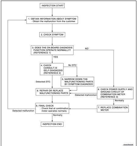
• Reference 1···MWI-22, "On Board Diagnosis Function".
• Reference 2···MWI-36, "DTC Index".
• Reference 3···MWI-51, "COMBINATION METER : Diagnosis Procedure".
DETAILED FLOW
1.OBTAIN INFORMATION ABOUT SYMPTOM
Interview the customer to obtain as much information as possible about the conditions and environment under which the malfunction occurred.
>> GO TO 2.
2.CHECK SYMPTOM
• Check the symptom based on the information obtained from the customer.
• Check that any other malfunctions are present.
>> GO TO 3.
3.CHECK ON BOARD DIAGNOSIS OPERATION
Check that the on board diagnosis function operates. Refer to MWI-22, "On Board Diagnosis Function".
Does the on board diagnosis function operate normally? YES >> GO TO 4.
NO >> GO TO 6.
4.CHECK CONSULT-III SELF-DIAGNOSIS RESULTS
Connect CONSULT-III and perform self-diagnosis. Refer to MWI-36, "DTC Index".
Are self-diagnosis results normal? YES >> GO TO 5.
NO >> GO TO 8.
5.NARROW DOWN THE MALFUNCTIONING PARTS BY SYMPTOM DIAGNOSIS
Perform symptom diagnosis and narrow down the malfunctioning parts.
>> GO TO 8.
6.CHECK COMBINATION METER POWER SUPPLY AND GROUND CIRCUITS
Check combination meter power supply and ground circuits. Refer to MWI-51, "COMBINATION METER : Diagnosis Procedure".
Is inspection result OK? YES >> GO TO 7.
NO >> GO TO 8.
7.REPLACE COMBINATION METER
Replace combination meter.
>> GO TO 9.
8.REPAIR OR REPLACE MALFUNCTIONING PARTS
Repair or replace the malfunctioning parts.
NOTE
:
If DTC is displayed, erase DTC after repair or replace malfunctioning parts.
>> GO TO 9.
9.FINAL CHECK
Check that the combination meter operates normally.
Do they operate normally? YES >> INSPECTION END
NO >> GO TO 1.
 Wiring diagram
METER SYSTEM
Wiring Diagram
For connector terminal arrangements, harness layouts, and alphabets in a
(option abbreviation; if not
described in wiring diagram), refer to GI-12, "Connector Info ...

Other materials:
B263D, B263E, B263F intake door motor
DTC Logic
DTC DETECTION LOGIC
DTC CONFIRMATION PROCEDURE
1.PERFORM DTC CONFIRMATION PROCEDURE
With CONSULT-III
1. Turn ignition switch ON.
2. Select “Self Diagnostic Result” mode of “HVAC” using CONSULT-III.
3. Check DTC.
Is DTC detected?
YES >> Refer to HAC-159, "Dia ...
Power outlet
The power outlet is located in the instrument panel.
CAUTION
• The outlet and plug may be hot during or immediately after use.
• Do not use with accessories that exceed a 12 volt, 120W (10A) power draw. Do not
use double adapters or more than one electrical accessory.
• Use power ...
Intake manifold
Exploded View
1. Clamp
2. Water hose
3. PCV hose
4. Clamp
5. Gasket
6. Intake manifold
7. Clamp
8. Vacuum hose
9. Vacuum gallery assembly
10. Clamp
11. EVAP hose
12. EVAP service port valve
13. EVAP hose
14.EVAP canister purge volume control
solenoid valve
15. Bracket
16 ...
