Nissan Juke Service and Repair Manual : Wiring diagram
METER SYSTEM
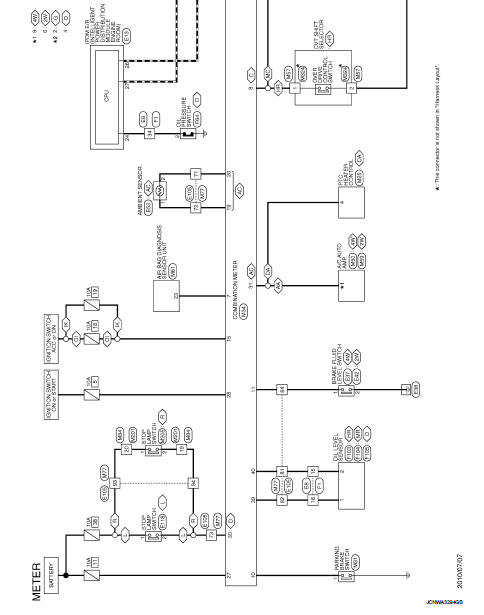
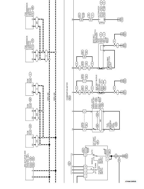
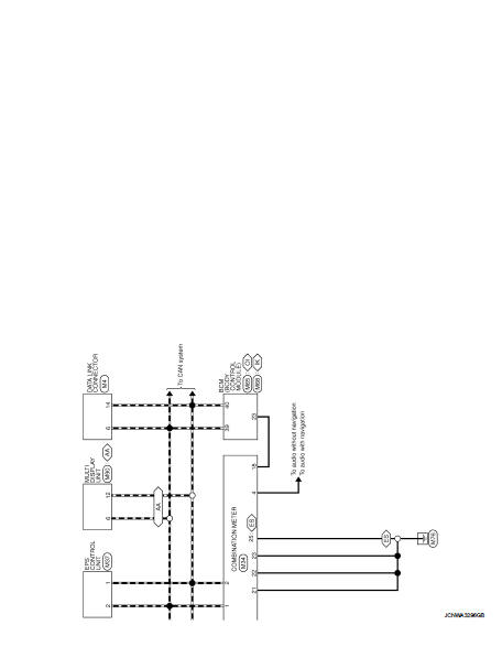
Wiring Diagram
For connector terminal arrangements, harness layouts, and alphabets in a
 (option abbreviation; if not
described in wiring diagram), refer to GI-12, "Connector Information/Explanation
of Option Abbreviation".
 IPDM E/R
List of ECU Reference
...
 Basic inspection
DIAGNOSIS AND REPAIR WORKFLOW (METER SYSTEM)
Work flow
OVERALL SEQUENCE
• Reference 1···MWI-22, "On Board Diagnosis Function".
• Reference 2···MWI-36, "DTC Index".
...
Other materials:
Luggage room lamp circuit
Description
Controls the luggage room lamp (ground side) to turn the luggage room lamp ON
and OFF.
Diagnosis Procedure
CAUTION:
Before performing the diagnosis, check that the following are normal.
• Interior room lamp power supply
• Luggage room lamp bulb
1.CHECK LUGGAGE ROOM LAMP OU ...
Wiring diagram
BCM
LHD
LHD : Wiring Diagram
For connector terminal arrangements, harness layouts, and alphabets in a
(option abbreviation; if not
described in wiring diagram), refer to GI-12, "Connector Information/Explanation
of Option Abbreviation".
RHD
RHD : Wiring Diagram
For con ...
Door does not lock/unlock with driver side door lock
knob or door key cylinder
Diagnosis Procedure
1.CHECK POWER DOOR LOCK OPERATION
Check power door lock operation.
Does door lock/unlock with door lock and unlock switch?
YES >> GO TO 2.
NO >> Refer to DLK-254, "Component Function Check".
2.CHECK UNLOCK SENSOR
Check unlock sensor.
Refer to ...
