Nissan Juke Service and Repair Manual : IPDM E/R
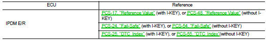
List of ECU Reference
 Combination meter
Reference Value
VALUES ON THE DIAGNOSIS TOOL
NOTE:
Some items are not available according to vehicle specification.
TERMINAL LAYOUT
PHYSICAL VALUES
Fail-Safe
FAIL-SAFE
The ...
 Wiring diagram
METER SYSTEM
Wiring Diagram
For connector terminal arrangements, harness layouts, and alphabets in a
(option abbreviation; if not
described in wiring diagram), refer to GI-12, "Connector Info ...
Other materials:
B26FA cranking request circuit
DTC Logic
DTC DETECTION LOGIC
NOTE:
• If DTC B26FA is displayed with DTC U1000, first perform the trouble diagnosis
for DTC U1000. Refer to
BCS-83, "DTC Logic".
• If DTC B26FA is displayed with DTC U1010, first perform the trouble diagnosis
for DTC U1010. Refer to
BCS-84, &qu ...
Power supply and ground circuit
Diagnosis Procedure
1.CHECK FUSES AND FUSIBLE LINK
Check that the following fuses and fusible link are not fusing.
Is the fuse fusing?
YES >> Replace the blown fuse or fusible link after repairing the affected
circuit if a fuse or fusible link is
blown.
NO >> GO TO 2.
2.CH ...
Vehicle Dynamic Control (VDC) system
The Vehicle Dynamic Control (VDC) system in your Nissan Leaf serves as a comprehensive safety net, utilizing an array of sophisticated sensors to continuously monitor driver inputs, such as steering and braking, alongside the actual motion and attitude of the vehicle.
Under challengin ...
