Nissan Juke Service and Repair Manual : Chassis maintenance
Headlamp aiming adjustment (halogen type - LHD)
HEADLAMP AIMING ADJUSTMENT (HALOGEN TYPE - LHD) : Description
PREPARATION BEFORE ADJUSTING
NOTE
:
ŌĆó For details, refer to the regulations in your own country.
ŌĆó Perform aiming if the vehicle front body has been repaired and/or the headlamp assembly has been replaced.
Before performing aiming adjustment, check the following.
ŌĆó Adjust the tire pressure to the specification.
ŌĆó Fill with fuel, engine coolant and each oil.
ŌĆó Maintain the unloaded vehicle condition. (Remove luggage from the passenger compartment and the luggage room.)
NOTE
:
Do not remove the temporary tire, jack and on-vehicle tool.
ŌĆó Wipe out dirt on the headlamp.
CAUTION:
Never use organic solvent (thinner, gasoline etc.)
ŌĆó Ride alone on the driver seat.
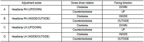
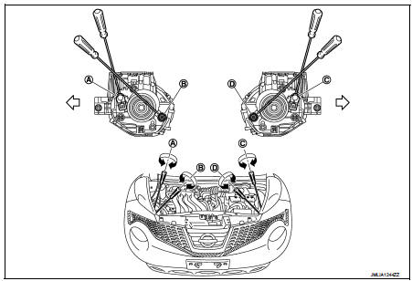
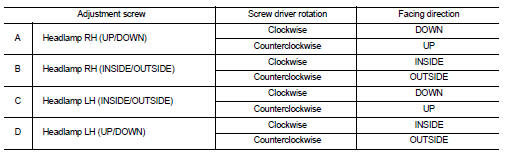
AIMING ADJUSTMENT SCREW
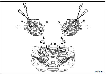
A. Headlamp RH (INSIDE/OUTSIDE)
adjustment screw
B. Headlamp RH (UP/DOWN)
adjustment screw
C. Headlamp LH (INSIDE/OUTSIDE)
adjustment screw
D. Headlamp LH (UP/DOWN)
adjustment screw
 : Vehicle center
HEADLAMP AIMING ADJUSTMENT (HALOGEN TYPE - LHD) : Aiming Adjustment Procedure
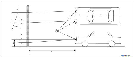
1. Place the screen.
NOTE
:
ŌĆó Stop the vehicle at the perpendicular angle to the wall.
ŌĆó Set the screen so that it is perpendicular to a level load surface.
2. Face the vehicle squarely toward the screen and make the distance between the headlamp center and the screen 10 m (32.8 ft).
3. Start the engine and illuminate the headlamp (LO).
NOTE
:
Block light from the headlamp that is not being adjusted with a thick fabric or
another object, so that it
does not reach the adjustment screen.
CAUTION:
Do not cover lens surface with tape, etc. because it is made from plastic.
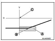
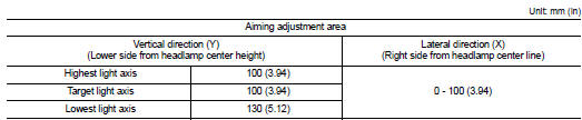
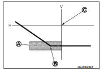
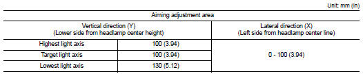
4. Use the aiming adjustment screw to adjust the elbow point projected by the low beams on the screen, so that it is within the aiming adjustment area.
Low beam distribution on the screen
A. Aiming adjustment area
B. Elbow point
C. Headlamp center
H. Horizontal center line of headlamp
V. Vertical center line of headlamp
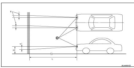
C. Vertical center line of headlamp
H. Horizontal center line of headlamp
L. Distance from headlamp center to screen
X. Aiming adjustment area
(lateral)
Y. Aiming adjustment area
(Vertical)
Distance from headlamp center to screen (L) : 10 m (32.8 ft)
Headlamp aiming adjustment (halogen type - RHD)
HEADLAMP AIMING ADJUSTMENT (HALOGEN TYPE - RHD) : Description
PREPARATION BEFORE ADJUSTING
NOTE
:
ŌĆó For details, refer to the regulations in your own country.
ŌĆó Perform aiming if the vehicle front body has been repaired and/or the headlamp assembly has been replaced.
Before performing aiming adjustment, check the following.
ŌĆó Adjust the tire pressure to the specification.
ŌĆó Fill with fuel, engine coolant and each oil.
ŌĆó Maintain the unloaded vehicle condition. (Remove luggage from the passenger compartment and the luggage room.)
NOTE
:
Do not remove the temporary tire, jack and on-vehicle tool.
ŌĆó Wipe out dirt on the headlamp.
CAUTION:
Never use organic solvent (thinner, gasoline etc.)
ŌĆó Ride alone on the driver seat.
AIMING ADJUSTMENT SCREW
A. Headlamp RH (INSIDE/OUTSIDE)
adjustment screw
B. Headlamp RH (UP/DOWN)
adjustment screw
C. Headlamp LH (INSIDE/OUTSIDE)
adjustment screw
D. Headlamp LH (UP/DOWN)
adjustment screw
 : Vehicle center
HEADLAMP AIMING ADJUSTMENT (HALOGEN TYPE - RHD) : Aiming Adjustment Procedure
1. Place the screen.
NOTE
:
ŌĆó Stop the vehicle at the perpendicular angle to the wall.
ŌĆó Set the screen so that it is perpendicular to a level load surface.
2. Face the vehicle squarely toward the screen and make the distance between the headlamp center and the screen 10 m (32.8 ft).
3. Start the engine and illuminate the headlamp (LO).
NOTE
:
Block light from the headlamp that is not being adjusted with a thick fabric or
another object, so that it
does not reach the adjustment screen.
CAUTION:
Do not cover lens surface with tape, etc. because it is made from plastic.
4. Use the aiming adjustment screw to adjust the elbow point projected by the low beams on the screen, so that it is within the aiming adjustment area.
Low beam distribution on the screen
A. Aiming adjustment area
B. Elbow point
C. Headlamp center
H. Horizontal center line of headlamp
V. Vertical center line of headlamp
C. Vertical center line of headlamp
H. Horizontal center line of headlamp
L. Distance from headlamp center to screen
X. Aiming adjustment area
(lateral)
Y. Aiming adjustment area
(Vertical)
Distance from headlamp center to screen (L) : 10 m (32.8 ft)
Exhaust system
EXHAUST SYSTEM : Inspection
Check exhaust pipes, muffler, and mounting for improper attachment, leakage, cracks, damage or deterioration.
ŌĆó If anything is found, repair or replace damaged parts.
CVT fluid (RE0F10B)
CVT FLUID (RE0F10B) : Inspection
CHECKING CVT FLUID
The fluid level should be checked with the fluid warmed up to 50 to 80┬░C (122 to 176┬░F). The fluid level check procedure is as follows: 1. Check for fluid leakage.
2. With the engine warmed up, drive the vehicle in an urban area.
When ambient temperature is 20┬░C (68┬░F), it takes about 10 minutes for the CVT fluid to warm up to 50 to 80┬░C (122 to 176┬░F).
3. Park the vehicle on a level surface.
4. Apply parking brake firmly.
5. With engine at idle, while depressing brake pedal, move shift selector throughout the entire shift range.
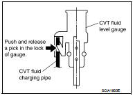
6. Pull out the CVT fluid level gauge from the CVT fluid charging pipe after pressing the tab on the CVT fluid level gauge to release the lock.
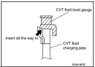
7. Wipe fluid off the CVT fluid level gauge. Insert the CVT fluid level gauge rotating 180┬░ from the originally installed position, then securely push the CVT fluid level gauge until it meets the top end of the CVT fluid charging pipe.
CAUTION:
When wiping away the CVT fluid level gauge, always use
lint-free paper, not a cloth rag.
8. Place the selector lever in ŌĆ£PŌĆØ or ŌĆ£NŌĆØ and check that the fluid level is within the specified range.
CAUTION:
When reinstalling CVT fluid level gauge, insert it into the
CVT fluid charging pipe and rotate it to the original installation
position until securely locked.
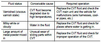
CVT FLUID CONDITION
Check CVT fluid condition.
ŌĆó If CVT fluid is very dark or smells burned, check operation of CVT.
Flush cooling system after repair of CVT.
ŌĆó If CVT fluid contains frictional material (clutches, brakes, etc.), replace radiator and flush cooler line using cleaning solvent and compressed air after repair of CVT. Refer to TM-297, "Exploded View".
CVT FLUID (RE0F10B) : Changing
CAUTION:
Replace drain plug gasket with new ones at the final stage of the operation when
installing.
1. Remove drain plug from oil pan.
2. Remove drain plug gasket from drain plug.
3. Install drain plug gasket to drain plug.
CAUTION:
Never reuse drain plug gasket.
4. Install drain plug to oil pan.
Drain plug ŌĆō tightening torque : Refer to TM-283, "Exploded View".
5. Fill CVT fluid from CVT fluid charging pipe to the specified level.
CVT fluid : Refer to TM-308, "General Specifica- Fluid capacity tion".
CAUTION:
ŌĆó Use only Genuine NISSAN CVT Fluid NS-2. Never mix with other fluid.
ŌĆó Using CVT fluid other than Genuine NISSAN CVT Fluid NS-2 will deteriorate in driveability and CVT durability, and may damage the CVT, which is not covered by the warranty.
ŌĆó When filling CVT fluid, take care not to scatter heat generating parts such as exhaust.
ŌĆó Sufficiently shake the container of CVT fluid before using.
ŌĆó Delete CVT fluid deterioration date with CONSULT-III after changing CVT fluid.
6. With the engine warmed up, drive the vehicle in an urban area.
NOTE
:
When ambient temperature is 20┬░C (68┬░F), it takes about 10 minutes for the CVT
fluid to warm up to 50 to
80┬░C (122 to 176┬░F).
7. Check CVT fluid level and condition.
8. Repeat steps 1 to 5 if CVT fluid has been contaminated.
CVT fluid (RE0F11A)
CVT FLUID (RE0F11A) : Inspection
FLUID LEAKAGE
ŌĆó Check transaxle surrounding area (oil seal and plug etc.)for fluid leakage.
ŌĆó If anything is found, repair or replace damaged parts and adjust CVT fluid level. Refer to TM-379, "Adjustment".
Gear oil (RS5F92R)
GEAR OIL (RS5F92R) : Inspection
OIL LEAKAGE
Make sure that gear oil is not leaking from transaxle or around it.
OIL LEVEL
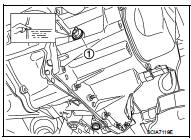
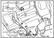
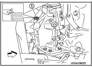
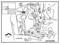
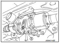
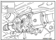
1. Remove filler plug (1) and gasket from transaxle case.
2. Check the oil level from filler plug mounting hole as shown in the figure.
CAUTION:
Never start engine while checking oil level.
3. Set a gasket on filler plug and then install it to transaxle case.
CAUTION:
Never reuse gasket.
4. Tighten filler plug to the specified torque. Refer to TM-33, "Exploded View".
GEAR OIL (RS5F92R) : Draining
1. Start engine and let it run to warm up transaxle.
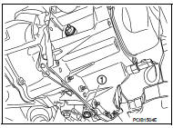
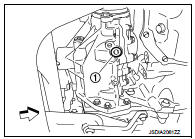
2. Stop engine. Remove drain plug (1) and gasket, using a socket [Commercial service tool] and then drain gear oil.
3. Set a gasket on drain plug and install it to clutch housing, using a socket [Commercial service tool].
CAUTION:
Never reuse gasket.
4. Tighten drain plug to the specified torque. Refer to TM-33, "Exploded View".
GEAR OIL (RS5F92R) : Refilling
1. Remove filler plug (1) and gasket from transaxle case.
2. Fill with new gear oil until oil level reaches the specified limit at filler plug mounting hole as shown in the figure.
Oil grade and viscosity : Refer to MA-13, "Fluids and Lubricants".
Oil capacity : Refer to TM-63, "General Specifications".
3. After refilling gear oil, check the oil level. Refer to MA-47, "GEAR OIL (RS5F92R) : Inspection".
4. Set a gasket on filler plug and then install it to transaxle case.
CAUTION:
Never reuse gasket.
5. Tighten filler plug to the specified torque. Refer to TM-33, "Exploded View".
Gear oil (RS6F94R)
GEAR OIL (RS6F94R) : Inspection
OIL LEAKAGE
Make sure that gear oil is not leaking from transaxle or around it.
OIL LEVEL
1. Remove filler plug (1) and gasket from transaxle case.
2. Check the oil level from filler plug mounting hole as shown in the figure.
CAUTION:
Never start engine while checking oil level.
3. Set a gasket on filler plug and then install it to transaxle case.
CAUTION:
Never reuse gasket.
4. Tighten filler plug to the specified torque. Refer to TM-88, "Exploded View".
GEAR OIL (RS6F94R) : Draining
1. Start engine and let it run to warm up transaxle.
2. Stop engine. Remove drain plug (1) and gasket, using a socket [Commercial service tool] and then drain gear oil.
3. Set a gasket on drain plug and install it to clutch housing, using a socket [Commercial service tool].
CAUTION:
Never reuse gasket.
4. Tighten drain plug to the specified torque. Refer to TM-88, "Exploded View".
GEAR OIL (RS6F94R) : Refilling
1. Remove filler plug (1) and gasket from transaxle case.
2. Fill with new gear oil until oil level reaches the specified limit at filler plug mounting hole as shown in the figure.
Oil grade and viscosity : Refer to MA-13, "Fluids and Lubricants".
Oil capacity : Refer to TM-123, "General Specifications".
3. After refilling gear oil, check the oil level. Refer to MA-48, "GEAR OIL (RS6F94R) : Inspection".
4. Set a gasket on filler plug and then install it to transaxle case.
CAUTION:
Never reuse gasket.
5. Tighten filler plug to the specified torque. Refer to TM-88, "Exploded View".
Clutch fluid (RS5F92R)
CLUTCH FLUID (RS5F92R) : Inspection
FLUID LEAKAGE
ŌĆó Check clutch line for cracks, deterioration or other damage. Replace any damaged parts.
ŌĆó Check for fluid leakage by fully depressing clutch pedal while engine is running.
CAUTION:
If leakage occurs around joints, reinstall the joints or, if necessary, replace
damaged parts.
FLUID LEVEL
ŌĆó Check that the fluid level in the reservoir tank is within the specified range (MAX ŌĆō MIN lines).
ŌĆó Visually check for any clutch fluid leakage around the reservoir tank.
ŌĆó Check the clutch system for any leakage if the fluid level is extremely low (lower than MIN)
Clutch fluid (RS6F94R)
CLUTCH FLUID (RS6F94R) : Inspection
FLUID LEAKAGE
ŌĆó Check clutch line for cracks, deterioration or other damage. Replace any damaged parts.
ŌĆó Check for fluid leakage by fully depressing clutch pedal while engine is running.
CAUTION:
If leakage occurs around joints, reinstall the joints or, if necessary, replace
damaged parts.
FLUID LEVEL
ŌĆó Check that the fluid level in the reservoir tank is within the specified range (MAX ŌĆō MIN lines).
ŌĆó Visually check for any clutch fluid leakage around the reservoir tank.
ŌĆó Check the clutch system for any leakage if the fluid level is extremely low (lower than MIN).
Transfer fluid
TRANSFER FLUID : Inspection
OIL LEAKAGE
Check transfer surrounding area (oil seal, drain plug, filler plug, and transfer case etc.) for oil leakage.
OIL LEVEL
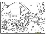
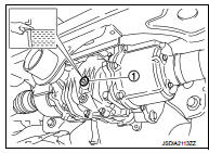
1. Remove filler plug (1) and gasket. Then check that oil is filled up from mounting hole for the filler plug.
 : Vehicle front
CAUTION:
Never start engine while checking oil level.
2. Before installing filler plug, set a new gasket. Install filler plug on transfer and tighten to the specified torque. Refer to DLN-113, "Exploded View".
CAUTION:
Never reuse gasket.
TRANSFER FLUID : Draining
1. Run the vehicle to warm up the transfer unit sufficiently.
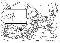
2. Stop the engine and remove the drain plug (1) and gascket to drain the transfer oil.
3. Before installing drain plug, set a new gasket. Install drain plug on the transfer and tighten to the specified torque. Refer to DLN- 113, "Exploded View".
: Vehicle front
CAUTION:
Never reuse gasket.
TRANSFER FLUID : Refilling
1. Remove filler plug (1) and gasket. Then fill oil up to mounting hole for the filler plug.
 : Vehicle front
Oil and viscosity : Refer to MA-13, "Fluids and Lubricants".
Oil capacity : Refer to DLN-117, "General Specifications".
CAUTION:
Carefully fill the oil. (Fill up for approximately 3 minutes.)
2. Leave the vehicle for 3 minutes, and check the oil level again.
3. Before installing filler plug, set a new gasket. Install filler plug on transfer and tighten to the specified torque. Refer to DLN-113, "Exploded View".
CAUTION:
Never reuse gasket.
Rear propeller shaft
REAR PROPELLER SHAFT : Inspection
APPEARANCE AND NOISE
ŌĆó Check the propeller shaft tube surface for dents or cracks. If damaged, replace propeller shaft assembly.
ŌĆó If center bearing is noisy or damaged, replace propeller shaft assembly.
VIBRATION
If vibration is present at high speed, inspect propeller shaft runout first.
1. With a dial indicator, measure propeller shaft runout at runout measuring points by rotating final drive companion flange with hands.
Propeller shaft runout : Refer to DLN-125, "Propeller Shaft Runout".
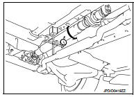
ŌĆó Propeller shaft runout measuring point (Point ŌĆ£
ŌĆØ)
 : Front
Dimension A: 542 mm (21.34 in) B: 516.5 mm (20.33 in)
2. If runout still exceeds specifications, separate propeller shaft at final drive companion flange or transfer companion flange; then change the phase between companion flange and propeller shaft by the one bolt hole at a time and install propeller shaft.
3. Check runout again. If runout still exceeds specifications, replace propeller shaft assembly.
4. Check the vibration by driving vehicle.
Rear differential gear oil
REAR DIFFERENTIAL GEAR OIL : Inspection
OIL LEAKAGE
Check rear final drive surrounding area (oil seal, drain plug, filler plug, and carrier case, etc.) for oil leakage.
OIL LEVEL
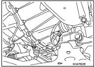
1. Remove filler plug (1) and check oil level from filler plug mounting hole as shown in the figure.
CAUTION:
Never start engine while checking oil level.
2. Set a new gasket on filler plug and install it on final drive assembly.
Refer to DLN-151, "Exploded View".
CAUTION:
Never reuse gasket.
REAR DIFFERENTIAL GEAR OIL : Draining
1. Stop engine.
2. Remove drain plug (1) and drain gear oil.
3. Set a new gasket on drain plug and install it to final drive assembly and tighten to the specified torque. Refer to DLN-151, "Exploded View".
CAUTION:
Never reuse gasket.
REAR DIFFERENTIAL GEAR OIL : Refilling
1. Remove filler plug (1). Fill with new gear oil until oil level reaches the specified level near filler plug mounting hole.
Oil grade and viscosity : Refer to MA-13, "Fluids and Lubricants".
Oil capacity : Refer to DLN-167, "General Specification".
2. After refilling oil, check oil level. Set a new gasket to filler plug, then install it to final drive assembly. Refer to DLN-151, "Exploded View".
CAUTION:
Never reuse gasket
Wheels (bonding weight type)
WHEELS (BONDING WEIGHT TYPE) : Adjustment
BALANCING WHEELS (ALUMINUM WHEEL)
Preparation Before Adjustment Using releasing agent, remove double-faced adhesive tape from the road wheel.
CAUTION:
ŌĆó Be careful not to scratch the road wheel during removal.
ŌĆó After removing double-faced adhesive tape, wipe clean traces of releasing agent from the road wheel.
Wheel Balance Adjustment ŌĆó The details of the adjustment procedure are different for each model of wheel balancer. Therefore, refer to each instruction manual.
ŌĆó If a tire balance machine has adhesion balance weight mode settings and drive-in weight mode setting, select and adjust a drive-in weight mode suitable for aluminum wheels.
1. Set road wheel on tire balance machine using the center hole as a guide. Start the tire balance machine.
2. When inner and outer unbalance values are shown on the tire balance machine indicator, multiply outer unbalance value by 5/3 to determine balance weight that should be used. Select the outer balance weight with a value closest to the calculated value above and install to the designated outer position of, or at the designated angle in relation to the road wheel.
CAUTION:
ŌĆó Never install the inner balance weight before installing the outer balance
weight.
ŌĆó Before installing the balance weight, always to clean the mating surface of the road wheel.
a. Indicated unbalance value × 5/3 = balance weight to be installed
Calculation example:
23 g (0.81 oz) × 5/3 = 38.33 g (1.35 oz) ⇒ 40 g (1.41 oz) balance
weight (closer to calculated balance weight value)
NOTE
:
Note that balance weight value must be closer to the calculated
balance weight value.
Example:
37.4 ⇒ 35 g (1.23 oz)
37.5 ⇒ 40 g (1.41 oz)
b. Installed balance weight in the position.
ŌĆó When installing balance weight (1) to road wheels, set it into the grooved area (A) on the inner wall of the road wheel as shown in the figure so that the balance weight center (B) is aligned with the tire balance machine indication position (angle) (C).
CAUTION:
ŌĆó Always use genuine NISSAN balance weights.
ŌĆó Balance weights are non-reusable; always replace with new ones.
ŌĆó Never install three or more sheets of balance weight
.
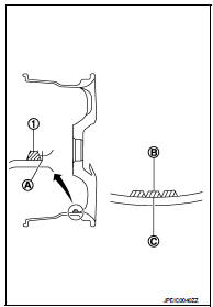
c. If calculated balance weight value exceeds 50 g (1.76 oz), install two balance weight sheets in line with each other as shown in the figure.
CAUTION:
Never install one balance weight sheet on top of another.
3. Start the tire balance machine again.
4. Install drive-in balance weight on inner side of road wheel in the tire balance machine indication position (angle).
CAUTION:
Never install three or more balance weight.
5. Start the tire balance machine. Check that the inner and outer residual unbalance value is within the allowable unbalance value.
CAUTION:
If either residual unbalance value exceeds limit, repeat installation
procedures.
Allowable unbalance value Dynamic (At flange) : Refer to WT-9, "Road Wheel".
Static (At flange) : Refer to WT-9, "Road Wheel".
BALANCING WHEELS (STEEL WHEEL)
Preparation Before Adjustment Remove balance weight from the road wheel.
Wheel Balance Adjustment ŌĆó The details of the adjustment procedure are different for each model of wheel balancer. Therefore, refer to each instruction manual.
ŌĆó If a tire balance machine has adhesion balance weight mode settings and drive-in weight mode setting, select and adjust a drive-in weight mode suitable for steel wheels.
1. Set road wheel to wheel balancer, and then start wheel balancer.
2. Install balance weight to road wheel according to the unbalance and position (angle) displayed on wheel balancer.
CAUTION:
ŌĆó Always use genuine NISSAN balance weights.
ŌĆó Balance weights are non-reusable; always replace with new ones.
ŌĆó Always use a plastic hammer when attaching the weight.
ŌĆó Never install three or more balance weights on one side.
3. Start the tire balance machine. Check that the inner and outer residual unbalance value is within the allowable unbalance value.
CAUTION:
If either residual unbalance value exceeds limit, repeat installation
procedures.
Allowable unbalance value Dynamic (At flange) : Refer to WT-9, "Road Wheel".
Static (At flange) : Refer to WT-9, "Road Wheel".
Brake fluid level and leaks
BRAKE FLUID LEVEL AND LEAKS : Inspection
ŌĆó If fluid level is extremely low, check brake system for leaks.
Brake lines and cables
BRAKE LINES AND CABLES : Inspection
ŌĆó Check brake fluid lines and parking brake cables for improper attachment, leaks, chafing, abrasions, deterioration, etc.
Brake fluid
BRAKE FLUID : Changing
1. Drain brake fluid from each bleed valve.
2. Refill until new brake fluid comes out from each bleed valve.
Use same procedure as in bleeding hydraulic system to refill brake fluid.
Refer to BR-13, "Bleeding Brake System" (LHD models), BR-81, "Bleeding Brake System" (RHD models).
ŌĆó Refill with recommended brake fluid.
Refer to MA-13, "Fluids and Lubricants".
ŌĆó Never reuse drained brake fluid.
ŌĆó Be careful not to splash brake fluid on painted areas.
Disc brake
DISC BRAKE : Inspection
DISC ROTOR
Check condition, wear, and damage.
CALIPER
ŌĆó Check for leakage
BRAKE PAD
ŌĆó Check for wear or damage.
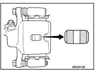
DISC BRAKE : Front Disc Brake
MR16DDT
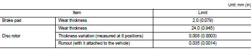
HR16DE, K9K

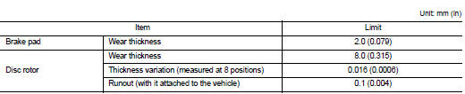
DISC BRAKE : Rear Disc Brake
Steering gear and linkage
STEERING GEAR AND LINKAGE : Inspection
STEERING GEAR
ŌĆó Check gear housing and boots for looseness, damage and grease leakage.
ŌĆó Check connection with steering column for looseness.

STEERING LINKAGE
Check ball joint, dust cover and other component parts for looseness, wear, damage and grease leakage.
Axle and suspension parts
AXLE AND SUSPENSION PARTS : Inspection
Check front and rear axle and suspension parts for excessive play, cracks, wear or other damage.
ŌĆó Shake each wheel to check for excessive play.
ŌĆó Check wheel bearings for smooth operation.
ŌĆó Check axle and suspension nuts and bolts for looseness.
ŌĆó Check strut (shock absorber) for oil leakage or other damage.
ŌĆó Check suspension ball joint for grease leakage and ball joint dust cover for cracks or other damage
Drive shaft
DRIVE SHAFT : Inspection
Check boot and drive shaft for cracks, wear, damage and grease leakage.
 Engine maintenance (K9K)
Drive belt
DRIVE BELT : Checking Drive Belts
WARNING:
Be sure to perform when the engine is stopped.
1. Inspect belts for cracks, fraying, wear and oil. If necessary,
replace.
2. Evaluate manu ...
 Body maintenance
Locks, hinges and hood latch
LOCKS, HINGES AND HOOD LATCH : Lubr
Seat belt, buckles, retractors, anchors and adjusters
SEAT BELT, BUCKLES, RETRACTORS, ANCHORS AND ADJUSTERS : Inspection
For fron ...
Other materials:
Wiring diagram
METER SYSTEM
Wiring Diagram
For connector terminal arrangements, harness layouts, and alphabets in a
(option abbreviation; if not
described in wiring diagram), refer to GI-12, "Connector Information/Explanation
of Option Abbreviation".
...
C1101, C1102, C1103, C1104 WHEEL SENSOR
DTC Logic
DTC DETECTION LOGIC
DTC CONFIRMATION PROCEDURE
1.PRECONDITIONING
If ŌĆ£DTC CONFIRMATION PROCEDUREŌĆØ has been previously conducted, always turn
ignition switch OFF and
wait at least 10 seconds before conducting the next test.
>> GO TO 2.
2.CHECK DTC DETECTION
With CON ...
Cold weather driving
CAUTION
To maintain the long-term integrity and health of your Nissan Leaf Li-ion battery, it is crucial that you do not store the vehicle in ambient temperatures below -13┬║F (-25┬║C) for a duration exceeding seven days. When the external temperature reaches -13┬║F (-25┬║C) or lower, the batte ...
