Nissan Juke Service and Repair Manual : P1829 accelerator pedal position sensor
DTC Logic
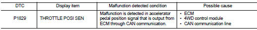
DTC DETECTION LOGIC
DTC CONFIRMATION PROCEDURE
1.PRECONDITIONING
If тАЬDTC CONFIRMATION PROCEDUREтАЭ has been previously conducted, always turn ignition switch OFF and wait at least 10 seconds before conducting the next test.
>> GO TO 2.
2.DTC REPRODUCTION PROCEDURE
 With CONSULT-III
1. Start the engine and drive at 30 km/h (19 MPH) or more.
2. Perform self-diagnosis for тАЬALL MODE AWD/4WDтАЭ.
Is DTC тАЬP1829тАЭ detected? YES >> Proceed to diagnosis procedure. Refer to DLN-53, "Diagnosis Procedure".
NO >> INSPECTION END
Diagnosis Procedure
1.PERFORM ECM SELF-DIAGNOSIS
 With CONSULT-III
Perform self-diagnosis for тАЬENGINEтАЭ.
Is any DTCs detected? YES >> Check the DTCs. Refer to EC-108, "DTC Index".
NO >> GO TO 2.
2.ERASE SELF-DIAGNOSTIC RESULT
 With CONSULT-III
1. Erase self-diagnostic results for тАЬALL MODE AWD/4WDтАЭ.
2. Turn the ignition switch OFF.
3. Start the engine and drive vehicle for a while.
4. Check that malfunction indicator lamp (MIL) turns OFF.
Does malfunction indicator lamp (MIL) turn OFF? YES >> GO TO 3.
NO >> Refer to EC-436, "Diagnosis Procedure".
3.CHECK TERMINALS AND HARNESS CONNECTORS
Check 4WD control module pin terminals for damage or loose connection with harness connector.
Is inspection result normal? YES >> After turning the ignition switch OFF, perform DTC confirmation procedure again. When DTC тАЬP1829тАЭ is detected, Replace 4WD control module. Refer to DLN-91, "Removal and Installation".
NO >> Repair or replace error-detected parts
 P1820 engine speed signal
DTC Logic
DTC DETECTION LOGIC
DTC CONFIRMATION PROCEDURE
1.PRECONDITIONING
If тАЬDTC CONFIRMATION PROCEDUREтАЭ has been previously conducted, always turn
ignition switch OFF and
wait at least ...
 P182D 4WD solenoid left
DTC Logic
DTC DETECTION LOGIC
DTC CONFIRMATION PROCEDURE
1.PRECONDITIONING
If тАЬDTC CONFIRMATION PROCEDUREтАЭ has been previously conducted, always turn
ignition switch OFF and
wait at least ...
Other materials:
Component parts
Component Parts Location
1. Remote keyless entry receiver
Refer to DLK-361,
"Component Parts Location" (With
super lock) or DLK-492,
"Component Parts Location" (Without
super lock).
2. Combination meter
Refer to MWI-4, "METER SYSTEM :
Component Parts Location" ...
Precaution for Supplemental Restraint System (SRS) "AIR BAG" and "SEAT BELT
PRE-TENSIONER"
The Supplemental Restraint System such as тАЬAIR BAGтАЭ and тАЬSEAT BELT PRE-TENSIONERтАЭ,
used along
with a front seat belt, helps to reduce the risk or severity of injury to the
driver and front passenger for certain
types of collision. Information necessary to service the system safely is
...
Normal operating condition
Description
FRONT WIPER MOTOR PROTECTION FUNCTION
тАв IPDM E/R may stop the front wiper to protect the front wiper motor if any
obstruction (operation resistance)
such as a large amount of snow is detected during the front wiper operation.
тАв At that time turn OFF the front wiper and remove t ...
