Nissan Juke Service and Repair Manual : P182D 4WD solenoid left
DTC Logic
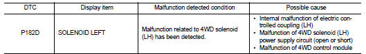
DTC DETECTION LOGIC
DTC CONFIRMATION PROCEDURE
1.PRECONDITIONING
If ÔÇťDTC CONFIRMATION PROCEDUREÔÇŁ has been previously conducted, always turn ignition switch OFF and wait at least 10 seconds before conducting the next test.
>> GO TO 2.
2.DTC REPRODUCTION PROCEDURE (1)
 With CONSULT-III
1. Turn the ignition switch OFF to ON, and then wait for 5 seconds or more.
2. Turn the ignition switch OFF.
3. Turn the ignition switch ON, and then wait for 5 seconds or more.
4. Perform self-diagnosis for ÔÇťALL MODE AWD/4WDÔÇŁ.
Is DTC ÔÇťP182DÔÇŁ detected? YES >> Proceed to diagnosis procedure. Refer to DLN-54, "Diagnosis Procedure".
NO >> GO TO 3.
3.DTC REPRODUCTION PROCEDURE (2)
 With CONSULT-III
1. Lift up the vehicle.
2. Start the engine, and run at idle for 1 second.
3. Perform self-diagnosis for ÔÇťALL MODE AWD/4WDÔÇŁ.
Is DTC ÔÇťP182DÔÇŁ detected? YES >> Proceed to diagnosis procedure. Refer to DLN-54, "Diagnosis Procedure".
NO >> GO TO 4.
4.DTC REPRODUCTION PROCEDURE (3)
 With CONSULT-III
1. Drive the vehicle at 30 km/h (19 MPH) or more less for approximately 1 minute.
2. Stop the vehicle.
3. Drive the vehicle at 30 km/h (19 MPH) or more less for approximately 1 minute.
4. Perform self-diagnosis for ÔÇťALL MODE AWD/4WDÔÇŁ.
Is DTC ÔÇťP182DÔÇŁ detected? YES >> Proceed to diagnosis procedure. Refer to DLN-54, "Diagnosis Procedure".
NO >> INSPECTION END
Diagnosis Procedure
1.CHECK 4WD SOLENOID CIRCUIT (1)
1. Check the resistance between 4WD control module harness connector
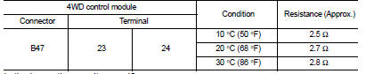
Is the inspection result normal? YES >> GO TO 4.
NO >> GO TO 2.
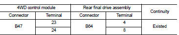
2.CHECK 4WD SOLENOID CIRCUIT (2)
1. Check the continuity between 4WD control module harness connector and rear final drive assembly harness connector.
2. Check the continuity between 4WD control module harness connector and the ground.
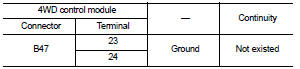
Is the inspection result normal? YES >> GO TO 3.
NO >> Repair or replace the error-detected parts.
3.CHECK 4WD SOLENOID
Check 4WD solenoid. Refer to DLN-55, "Component Inspection".
Is the inspection result normal? YES >> GO TO 4.
NO >> 4WD solenoid is malfunctioning (LH). Replace electric controlled coupling. Refer to DLN-139, "Removal and Installation".
4.CHECK TERMINALS AND HARNESS CONNECTORS
1. Check 4WD control module pin terminals for damage or loose connection with harness connector.
2. Check rear final drive assembly pin terminals for damage or loose connection with harness connector.
Is the inspection result normal? YES >> Replace 4WD control module. Refer to DLN-91, "Removal and Installation".
NO >> Repair or replace the error-detected parts.
Component Inspection
1.CHECK 4WD SOLENOID
1. Turn the ignition switch OFF.
2. Disconnect rear final drive assembly harness connector.
3. Check the resistance between rear final drive assembly connector terminals.
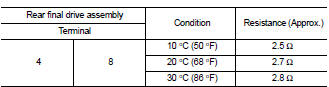
Is the inspection result normal? YES >> INSPECTION END
NO >> 4WD solenoid (LH) is malfunctioning. Replace electric controlled coupling. Refer to DLN-139, "Removal and Installation".
 P1829 accelerator pedal position sensor
DTC Logic
DTC DETECTION LOGIC
DTC CONFIRMATION PROCEDURE
1.PRECONDITIONING
If ÔÇťDTC CONFIRMATION PROCEDUREÔÇŁ has been previously conducted, always turn
ignition switch OFF and
wait at least ...
 P182E 4WD solenoid right
DTC Logic
DTC DETECTION LOGIC
1.PRECONDITIONING
If ÔÇťDTC CONFIRMATION PROCEDUREÔÇŁ has been previously conducted, always turn
ignition switch OFF and
wait at least 10 seconds before conductin ...
Other materials:
Intelligent Around View Monitor
system operation
To display the multiple synchronized perspective views, the advanced Intelligent Around View Monitor system utilizes a network of four ultra-wide-angle digital cameras strategically located in the center of the front grille assembly, embedded on the lower housings of the vehicl ...
Diagnosis and repair work flow
Work Flow
OVERALL SEQUENCE
DETAILED FLOW
1.GET INFORMATION ABOUT SYMPTOM
Get the detailed information from the customer about the symptom (the
condition and the environment when
the incident/malfunction occurred).
>> GO TO 2.
2.CHECK DTC
1. Check DTC for ÔÇťENGINEÔÇŁ and ÔÇťBCM ...
Diagnosis system (BCM)
Common item : consult-III Function (BCM - COMMON ITEM)
APPLICATION ITEM
CONSULT-III performs the following functions via CAN communication with BCM.
SYSTEM APPLICATION
BCM can perform the following functions for each system.
NOTE:
It can perform the diagnosis modes except the following for ...
