Nissan Juke Service and Repair Manual : P182E 4WD solenoid right
DTC Logic
DTC DETECTION LOGIC
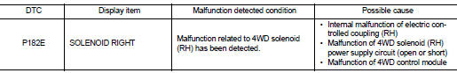
1.PRECONDITIONING
If “DTC CONFIRMATION PROCEDURE” has been previously conducted, always turn ignition switch OFF and wait at least 10 seconds before conducting the next test.
>> GO TO 2.
2.DTC REPRODUCTION PROCEDURE (1)
 With CONSULT-III
1. Turn the ignition switch OFF to ON, and then wait for 5 seconds or more.
2. Turn the ignition switch OFF.
3. Turn the ignition switch ON, and then wait for 5 seconds or more.
4. Perform self-diagnosis for “ALL MODE AWD/4WD”.
Is DTC “P182E” detected? YES >> Proceed to diagnosis procedure. Refer to DLN-57, "Diagnosis Procedure".
NO >> GO TO 3.
3.DTC REPRODUCTION PROCEDURE (2)
 With CONSULT-III
1. Lift up the vehicle.
2. Start the engine, and run at idle for 1 second.
3. Perform self-diagnosis for “ALL MODE AWD/4WD”.
Is DTC “P182E” detected? YES >> Proceed to diagnosis procedure. Refer to DLN-57, "Diagnosis Procedure".
NO >> GO TO 4.
4.DTC REPRODUCTION PROCEDURE (3)
 With CONSULT-III
1. Drive the vehicle at 30 km/h (19 MPH) or more less for approximately 1 minute.
2. Stop the vehicle.
3. Drive the vehicle at 30 km/h (19 MPH) or more less for approximately 1 minute.
4. Perform self-diagnosis for “ALL MODE AWD/4WD”.
Is DTC “P182E” detected? YES >> Proceed to diagnosis procedure. Refer to DLN-57, "Diagnosis Procedure".
NO >> INSPECTION END
Diagnosis Procedure
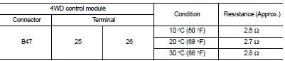
1.CHECK 4WD SOLENOID CIRCUIT (1)
1. Check the resistance between 4WD control module harness connector.
Is the inspection result normal? YES >> GO TO 4.
NO >> GO TO 2.
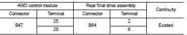
2.CHECK 4WD SOLENOID CIRCUIT (2)
1. Check the continuity between 4WD control module harness connector and rear final drive assembly harness connector.
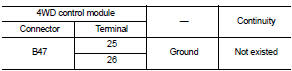
2. Check the continuity between 4WD control module harness connector and the ground.
Is the inspection result normal? YES >> GO TO 3.
NO >> Repair or replace the error-detected parts.
3.CHECK 4WD SOLENOID
Check 4WD solenoid. Refer to DLN-58, "Component Inspection".
Is the inspection result normal? YES >> GO TO 4.
NO >> 4WD solenoid is malfunctioning (RH). Replace electric controlled coupling. Refer to DLN-139, "Removal and Installation".
4.CHECK TERMINALS AND HARNESS CONNECTORS
1. Check 4WD control module pin terminals for damage or loose connection with harness connector.
2. Check rear final drive assembly pin terminals for damage or loose connection with harness connector.
Is the inspection result normal? YES >> Replace 4WD control module. Refer to DLN-91, "Removal and Installation".
NO >> Repair or replace the error-detected parts.
Component Inspection
1.CHECK 4WD SOLENOID
1. Turn the ignition switch OFF.
2. Disconnect rear final drive assembly harness connector.
3. Check the resistance between rear final drive assembly connector terminals.
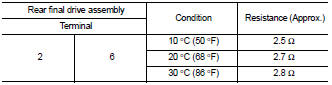
Is the inspection result normal? YES >> INSPECTION END
NO >> 4WD solenoid (RH) is malfunctioning. Replace electric controlled coupling. Refer to DLN-139, "Removal and Installation".
 P182D 4WD solenoid left
DTC Logic
DTC DETECTION LOGIC
DTC CONFIRMATION PROCEDURE
1.PRECONDITIONING
If “DTC CONFIRMATION PROCEDURE” has been previously conducted, always turn
ignition switch OFF and
wait at least ...
 P182F coupling temperature sensor left
DTC Logic
DTC DETECTION LOGIC
DTC CONFIRMATION PROCEDURE
1.PRECONDITIONING
If “DTC CONFIRMATION PROCEDURE” has been previously conducted, always turn
ignition switch OFF and
wait at least ...
Other materials:
B1106, B1107, B1108, B1109, B1110, B1111 diagnosis sensor unit
DTC Logic
DTC DETECTION LOGIC
DTC CONFIRMATION PROCEDURE
1.CHECK SELF-DIAG RESULT
With CONSULT-III
1. Turn ignition switch ON.
2. Perform “Self Diagnostic Result” mode of “AIR BAG” using CONSULT-III.
Without CONSULT-III
1. Turn ignition switch ON.
2. Check the air bag warning la ...
P1551, P1552 battery current sensor
DTC Logic
DTC DETECTION LOGIC
DTC CONFIRMATION PROCEDURE
1.PRECONDITIONING
If DTC Confirmation Procedure has been previously conducted, always perform
the following before conducting
the next test.
1. Turn ignition switch OFF and wait at least 10 seconds.
2. Turn ignition switch ON.
3. ...
Precaution
Precaution for Supplemental Restraint System (SRS) "AIR BAG" and "SEAT
BELT
PRE-TENSIONER"
The Supplemental Restraint System such as “AIR BAG” and “SEAT BELT PRE-TENSIONER”,
used along
with a front seat belt, helps to reduce the risk or severity of injury to the
...
