Nissan Juke Service and Repair Manual : Door mirror defogger
Description
Heats the heating wire with the power supply from the rear window defogger relay to prevent the door mirror from fogging up.
Component Function Check
1.CHECK DOOR MIRROR DEFOGGER
1. Perform IPDM E/R Active Test (“REAR DEFOGGER”) using CONSULT-III.
2. Touch “ON”.
3. Check that both side door mirror glasses are getting warmer.
Is the inspection result normal? YES >> Door mirror defogger is OK.
NO >> Refer to DEF-34, "Diagnosis Procedure"
Diagnosis Procedure
1.CHECK FUSE
1. Turn ignition switch OFF.
2. Check 10A fuse [No.22, located in fuse block (J/B)].
Is the inspection result normal? YES >> GO TO 2.
NO >> Replace the blown fuse after repairing the affected circuit if a fuse is blown.
2.CHECK DOOR MIRROR DEFOGGER CIRCUIT
1. Disconnect IPDM E/R connector and door mirror (both sides) connector.
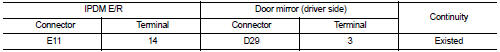
2. Check continuity between IPDM E/R harness connector and door mirror (driver side) harness connector.
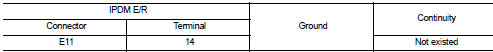
3. Check continuity between IPDM E/R harness connector and ground.
Is the inspection result normal? YES >> GO TO 3.
NO >> Repair or replace harness.
3.CHECK INTERMITTENT INCIDENT
Check intermittent incident.
Refer to GI-42, "Intermittent Incident".
>> INSPECTION END
 Rear window defogger
Description
Heats the heating wire with the power supply from the rear window defogger
relay to prevent the rear window
from fogging up.
Component Function Check
1.CHECK FUNCTION
1. Perform IPD ...
 Driver side door mirror defogger
Description
Heats the heating wire with the power supply from the rear window defogger
relay to prevent the door mirror
from fogging up.
Component Function Check
1.CHECK DRIVER SIDE DOOR MIRROR ...
Other materials:
P0444 EVAP canister purge volume control solenoid valve
DTC Logic
DTC DETECTION LOGIC
DTC CONFIRMATION PROCEDURE
1.CONDITIONING
If DTC Confirmation Procedure has been previously conducted, always turn
ignition switch OFF and wait at
least 10 seconds before conducting the next test.
TESTING CONDITION:
Before performing the following procedure ...
Configuration (bcm)
Description
Vehicle specification needs to be written with CONSULT-III because it is not
written after replacing BCM.
Configuration has three functions as follows.
NOTE:
Manual setting item: Items which need selection by vehicle specifications
Automatic setting item: Items which are written ...
Horn
To alert other drivers, simply push the center pad area of the steering wheel to sound the horn.
WARNING
Do not attempt to disassemble the horn assembly. Any unauthorized tampering could interfere with the critical operation of the supplemental front air bag system, w ...
