Nissan Juke Service and Repair Manual : Driver side door mirror defogger
Description
Heats the heating wire with the power supply from the rear window defogger relay to prevent the door mirror from fogging up.
Component Function Check
1.CHECK DRIVER SIDE DOOR MIRROR DEFOGGER
1. Perform IPDM E/R Active Test (“REAR DEFOGGER”) using CONSULT-III.
2. Touch “ON”.
3. Check that the driver side door mirror glass is getting warmer.
Is the inspection result normal? YES >> Driver side door mirror defogger is OK.
NO >> Refer to DEF-35, "Diagnosis Procedure"
Diagnosis Procedure
1.CHECK POWER SUPPLY CIRCUIT
1. Turn ignition switch OFF.
2. Disconnect door mirror (driver side) connector.
3. Turn ignition switch ON.
4. Check voltage between door mirror (driver side) harness connector and ground.
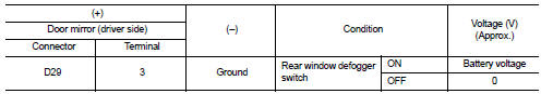
Is the inspection result normal? YES >> GO TO 2.
NO >> Repair or replace harness.
2.CHECK GROUND CIRCUIT
1. Turn ignition switch OFF.
2. Check continuity between door mirror (driver side) harness connector and ground.
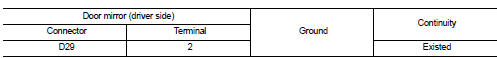
Is the inspection result normal? YES >> Replace door mirror glass (driver side). Refer to MIR-44, "GLASS MIRROR : Removal and Installation" NO >> Repair or replace harness.
 Door mirror defogger
Description
Heats the heating wire with the power supply from the rear window defogger
relay to prevent the door mirror
from fogging up.
Component Function Check
1.CHECK DOOR MIRROR DEFOGGER
1. ...
 Passenger side door mirror defogger
Description
Heats the heating wire with the power supply from the rear window defogger
relay to prevent the door mirror
from fogging up.
Component Function Check
1.CHECK PASSENGER SIDE DOOR MIRR ...
Other materials:
Push-button ignition switch
Component Function Check
1.CHECK FUNCTION
1. Select “PUSH SW” in “Data Monitor” mode with CONSULT-III.
2. Check the push-button ignition switch signal under the following conditions.
Is the indication normal?
YES >> INSPECTION END.
NO >> Go to PCS-108, "Diagnosis Pro ...
ABS branch line circuit
Diagnosis Procedure
1.CHECK CONNECTOR
1. Turn the ignition switch OFF.
2. Disconnect the battery cable from the negative terminal.
3. Check the terminals and connectors of the ABS actuator and electric unit
(control unit) for damage, bend
and loose connection (unit side and connector side).
...
Precaution
Precaution for Supplemental Restraint System (SRS) "AIR BAG" and "SEAT
BELT
PRE-TENSIONER"
The Supplemental Restraint System such as “AIR BAG” and “SEAT BELT PRE-TENSIONER”,
used along
with a front seat belt, helps to reduce the risk or severity of injury to the
...
