Nissan Juke Service and Repair Manual : Rear window defogger
Description
Heats the heating wire with the power supply from the rear window defogger relay to prevent the rear window from fogging up.
Component Function Check
1.CHECK FUNCTION
1. Perform IPDM E/R Active Test (“REAR DEFOGGER”) using CONSULT-III.
2. Touch “ON”.
3. Check that the rear window heating wire is getting warmer.
Is the inspection result normal? YES >> Rear window defogger is OK.
NO >> Refer to DEF-30, "Diagnosis Procedure"
Diagnosis Procedure
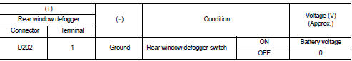
1.CHECK REAR WINDOW DEFOGGER POWER SUPPLY CIRCUIT
1. Turn ignition switch OFF.
2. Disconnect rear window defogger connector.
3. Turn ignition switch ON.
4. Check voltage between rear window defogger harness connector and ground.
Is the inspection result normal? YES >> GO TO 2.
NO >> GO TO 4.
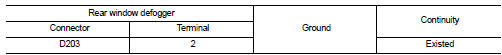
2.CHECK REAR WINDOW DEFOGGER GROUND CIRCUIT
1. Turn ignition switch OFF.
2. Check continuity between rear window defogger harness connector and ground.
Is the inspection result normal? YES >> GO TO 3.
NO >> Repair or replace harness.
3.CHECK FILAMENT
Refer to DEF-46, "Inspection and Repair".
Is the inspection result normal? YES >> GO TO 5.
NO >> Repair filament.
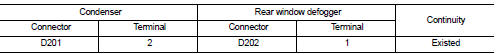
4.CHECK REAR WINDOW DEFOGGER POWER SUPPLY CIRCUIT 1
1. Turn ignition switch OFF.
2. Disconnect condenser connector.
3. Check continuity between condenser harness connector and rear window defogger harness connector.
4. Check continuity between condenser connector and ground.

Is the inspection result normal? YES >> GO TO 5.
NO >> Repair or replace harness.
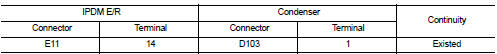
5.CHECK REAR WINDOW DEFOGGER POWER SUPPLY CIRCUIT 2
1. Disconnect IPDM E/R connectors.
2. Check continuity between IPDM E/R harness connector and condenser harness connector.
3. Check continuity between IPDM E/R connector and ground.
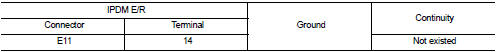
Is the inspection result normal? YES >> GO TO 6.
NO >> Repair or replace harness.
6.CHECK CONDENSER
Refer to DEF-32, "Component Inspection".
Is the inspection result normal? YES >> GO TO 7.
NO >> Replace condenser. Refer to DEF-48, "Removal and Installation".
7.CHECK INTERMITTENT INCIDENT
Refer to GI-42, "Intermittent Incident" Is the inspection result normal? YES >> INSPECTION END
NO >> Repair or replace harness or connector.
Component Inspection
1.CHECK CONDENSER
1. Turn ignition switch OFF.
2. Disconnect condenser connector.
3. Check continuity between condenser connector and ground part of condenser.
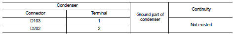
4. Check continuity between condenser terminals.

Is the inspection result normal? YES >> INSPECTION END
NO >> Replace condenser. Refer to DEF-48, "Removal and Installation".
 Rear window defogger relay
Description
The rear window defogger is operated by turning the rear window defogger
switch ON.
Component Function Check
1.CHECK FUNCTION
1. Perform IPDM E/R Active Test (“REAR DEFOGGER”) us ...
 Door mirror defogger
Description
Heats the heating wire with the power supply from the rear window defogger
relay to prevent the door mirror
from fogging up.
Component Function Check
1.CHECK DOOR MIRROR DEFOGGER
1. ...
Other materials:
Hazard switch
Component Function Check
1.CHECK HAZARD SWITCH SIGNAL BY CONSULT-III
CONSULT-III DATA MONITOR
1. Turn the ignition switch ON.
2. Select “HAZARD SW” of BCM (FLASHER) data monitor item.
3. With operating the hazard switch, check the monitor status.
Is the inspection result normal?
YES > ...
Air cleaner and air duct
Exploded View
1. Turbocharger air inlet pipe
2. Clamp
3. Air duct (suction)
4. Air mass flow sensor
5. O-ring
6. Air duct (inlet)
7. Grommet
8. Air cleaner case
9. Air cleaner filter
10. Cover
11. Holder
A. : To turbocharger
: Vehicle front
: N·m (kg-m, in-lb)
: Always repla ...
Back door opener switch
Component Function Check
1.CHECK FUNCTION
1. Select “TRUNK” of “BCM” using CONSULT-III.
2. Select “TRNK OPNR SW” in “DATA MONITOR” mode.
3. Check that the function operates normally according to the following
conditions.
Is the inspection result normal?
YES >> Back do ...
