Nissan Juke Service and Repair Manual : Drive belt idler pulley
Removal and Installation
REMOVAL
1. Remove drive belt. Refer to EM-155, "Removal and Installation".
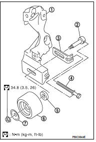
2. Remove the lock nut, and then remove the plate (7), idler pulley (6), and washer (5).
1 : Alternator bracket
3. Remove the center shaft (2) together with the spacer (3) with inserting the adjusting bolt (4).
INSTALLATION
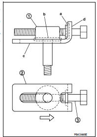
1. Insert the center shaft (1) into the slide groove of the spacer (2).
Fully screw in the adjusting bolt (3) in the belt loosening direction
( ).
).
• At that time, place the flange (a) of the adjusting bolt and the
seat (b) of the center shaft on the spacer.
2. Place each surface (c and d) of the spacer on the alternator bracket. Install the washer, idler pulley, and plate, and then temporarily tighten the lock nut.
 : 4.4 N·m (0.45 kg-m, 39 in-lb)
3. Install removed parts in the reverse order of removal.

 Air cleaner and air duct
Exploded View
1. Hose clamp
2. PCV hose
3. Hose clamp
4. Air cleaner filter
5. Air cleaner filter case
6. Grommet
7. Inlet air duct (lower)
8. Grommet
9. Inlet air duct (upper)
10. ...
Other materials:
Front coil spring and strut
Exploded View
2WD
1. Piston rod lock nut
2. Mounting insulator
3. Mounting bearing
4. Bound bumper
5. Coil spring
6. Lower rubber seat
7. Strut
8. Steering knuckle
: N·m (kg-m, ft-lb)
: Always replace after every
disassembly
4WD
1. Piston rod lock nut
2. Mounting insulator ...
Super lock does not operate
All door
ALL DOOR : Diagnosis Procedure
1.CHECK SUPER LOCK ACTUATOR
Check front driver side super lock actuator.
Refer to DLK-99, "DRIVER SIDE : Component Function Check".
Is the inspection result normal?
YES >> GO TO 2.
NO >> Repair or replace the malfunctioning p ...
Diagnosis and repair workflow
Gasoline engine models
GASOLINE ENGINE MODELS : Work Flow
OVERALL SEQUENCE
DETAILED FLOW
1.PRELIMINARY INSPECTION
Perform the preliminary inspection. Refer to CHG-17, "Inspection Procedure".
Models with battery current sensor>>GO TO 2.
Models without battery current sens ...
