Nissan Juke Service and Repair Manual : MR16DDT : Inspection and Adjustment
INSPECTION
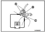
Magnetic Switch Check ŌĆó Before starting to check, disconnect the battery cable from the negative terminal.
ŌĆó Disconnect ŌĆ£MŌĆØ terminal of starter motor.
1. Continuity test [between ŌĆ£SŌĆØ terminal (A) and switch body]
B : ŌĆ£BŌĆØ terminal
C : ŌĆ£MŌĆØ terminal
ŌĆó Replace magnetic switch if continuity does not exist.
![2. Continuity test [between ŌĆ£SŌĆØ terminal (A) and ŌĆ£MŌĆØ terminal (C)]](images/books/335/22/index284.jpg)
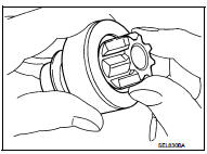
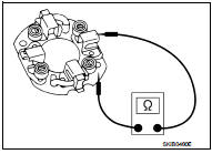
2. Continuity test [between ŌĆ£SŌĆØ terminal (A) and ŌĆ£MŌĆØ terminal (C)]
B : ŌĆ£BŌĆØ terminal
ŌĆó Replace magnetic switch if continuity does not exist.
Pinion/Clutch Check
1. Inspect pinion teeth.
ŌĆó Replace pinion if teeth are worn or damaged. (Also check condition of ring gear teeth.) 2. Inspect reduction gear teeth (If equipped).
ŌĆó Replace reduction gear if teeth are worn or damaged. (Also check condition of armature shaft gear teeth.) 3. Check to see if pinion locks in one direction and rotates smoothly in the opposite direction.
ŌĆó Replace pinion assembly if it is locked or rotated in both directions or unusual resistance is evident.
Brush Check
ŌĆó Check wear of brush.
Minimum length of brush : Refer to SDS STR-35, "Starter Motor".
ŌĆó Replace brush if the measurement value is less than the specified value.
Brush Spring Check
ŌĆó Check brush spring tension with brush spring detached from
brush.
Spring tension (with new brush) : Refer to SDS STR-35, "Starter Motor".
ŌĆó Replace brush spring if the measurement value is less than the specified value.
Brush Holder Check
1. Perform insulation test between brush holder (positive side) and
its base (negative side).
ŌĆó Replace brush holder assembly if continuity does not exist.
2. Check brush to see if it moves smoothly.
ŌĆó If brush holder is bent, replace it; if sliding surface is dirty, clean.
Yoke Check
Magnet is secured to yoke by bonding agent. Check magnet to see
that it is secured to yoke and for any cracks. Replace malfunctioning
parts as an assembly.
CAUTION:
Never clamp yoke in a vise or strike it with a hammer.
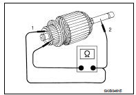
Armature Check
1. Continuity test (between two segments side by side)
ŌĆó Replace armature assembly if continuity does not exist.
2. Insulation test (between each commutator bar and shaft) ŌĆó Replace armature assembly if continuity exists.
3. Check commutator surface.
ŌĆó Grind with No. 500 - 600 emery paper if it has a rough surface.
4. Check diameter of commutator.
Commutator minimum diameter : Refer to SDS STR-35, "Starter Motor".
ŌĆó Replace armature assembly if the measurement value is less than the specified value.
5. Check depth of insulating mold from commutator surface.
ŌĆó Undercut to 0.5 to 0.8 mm (0.020 to 0.031 in) if the depth is 0.2 mm (0.008 in) or less.
ADJUSTMENT
Pinion Protrusion Length Adjustment
CLEARANCE
ŌĆó With pinion driven out by magnetic switch, push pinion back to
remove slack and measure clearance ŌĆ£LŌĆØ between the front edge
of the pinion and the pinion stopper.
Clearance ŌĆ£LŌĆØ : Refer to SDS STR-35, "Starter Motor".
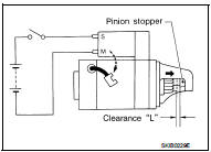
ŌĆó Adjust with the adjusting plate if the measurement value is not in the specified area.
 MR16DDT : Removal and Installation
REMOVAL
1. Disconnect the battery cable from the negative terminal. Refer to PG-124,
"Removal and Installation".
2. Drain engine coolant from radiator. Refer to CO-11, "Draining&quo ...
 Service data and specifications (SDS)
Starter Motor
...
Other materials:
Washer pump
Exploded View
1. Front washer nozzle LH
2. Front washer nozzle RH
3. Front washer tube LH
4. Front washer tube RH
5. Check valve
6. Front washer tube
7. Joint
8. Washer tank inlet cap
9. Washer tank inlet
10. Washer tank
11. Headlamp washer pump
12. Washer pump
13. Packing
1 ...
Operating tips
ŌĆó When the shift lever is shifted to the R (Reverse) position, the monitor screen
automatically changes to the RearView Monitor mode. However, the radio can be heard.
ŌĆó When the view is switched, the display images on the screen may be displayed with
some delay.
ŌĆó When the temperature is ...
P182D 4WD solenoid left
DTC Logic
DTC DETECTION LOGIC
DTC CONFIRMATION PROCEDURE
1.PRECONDITIONING
If ŌĆ£DTC CONFIRMATION PROCEDUREŌĆØ has been previously conducted, always turn
ignition switch OFF and
wait at least 10 seconds before conducting the next test.
>> GO TO 2.
2.DTC REPRODUCTION PROCEDURE (1 ...
