Nissan Juke Service and Repair Manual : Air cleaner and air duct
Exploded View
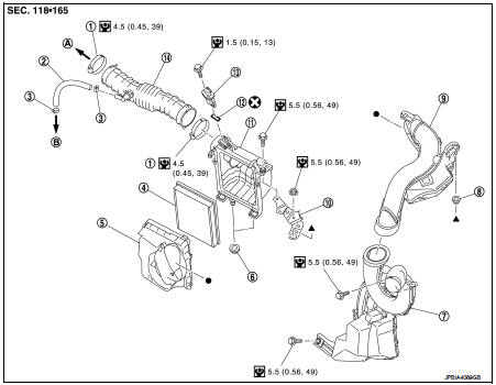
1. Hose clamp
2. PCV hose
3. Hose clamp
4. Air cleaner filter
5. Air cleaner filter case
6. Grommet
7. Inlet air duct (lower)
8. Grommet
9. Inlet air duct (upper)
10. Bracket
11. Air cleaner case
12. O-ring
13. Mass air flow sensor
14. Air duct
A. To electric throttle control actuator B. To rocker cover
 : Always replace after every
disassembly.
 : N┬Ęm (kg-m, in-lb)
Removal and Installation
REMOVAL
NOTE
:
Mass air flow sensor is removable under the car-mounted condition.
1. Remove the clip of front fender protector (left) to lift the front fender protector.
2. Remove the front side glille (left) from front bumper.
3. Remove installing bolts from inlet air duct (lower).
4. Disconnect mass air flow sensor harness connector.
5. Loosen the hose clamp of air duct.
6. Remove installing bolts from air cleaner case.
7. Remove inlet air duct (upper) and air cleaner simultaneously 8. Remove inlet air duct (lower) 9. .Disconnect PCV hose.
10. Remove air duct.
11. Remove mass air flow sensor from air cleaner case, if necessary.
CAUTION:
Handle the mass air flow sensor with following cares.
ŌĆó Never shock the mass air flow sensor.
ŌĆó Never disassemble the mass air flow sensor.
ŌĆó Never touch the sensor of the mass air flow sensor.
INSTALLATION
Note the following, and install in the reverse order of removal.
ŌĆó To install air duct, align the matching marks on both ends with the others.
1. : Electric throttle control actuator
2. : Air cleaner case
A. : Matching mark
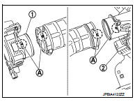
ŌĆó Align marks. Attach each joint. Screw clamps firmly.
Clamp tightening torque : 4.5 N┬Ęm (0.46 kg-m)
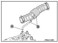
ŌĆó Install PVC hose with each matching mark positioned as follows:
A : White mark
B : Matching mark
Air duct side : Align the matching mark with that of air duct side.
Rocker cover side : Face the white mark in forward direction of the vehicle.
Inspection
INSPECTION AFTER REMOVAL
Inspect air duct for crack or tear.
ŌĆó If anything found, replace air duct.
 Drive belt idler pulley
Removal and Installation
REMOVAL
1. Remove drive belt. Refer to EM-155, "Removal and Installation".
2. Remove the lock nut, and then remove the plate (7), idler pulley
(6), and washer (5 ...
 Intake manifold
Exploded View
1. EVAP canister purge volume control
solenoid valve
2. Hose clamp
3. Vacuum hose
4. Intake manifold support
5. Gasket
6. Intake manifold
7. Electric throttle control actua ...
Other materials:
Component parts
Component Parts Location
1. Hazard switch
2. Parking lamp
3. Front turn signal lamp
4. Front fog lamp*1
5. Headlamp
6. ECM
Refer to EC-461, "ECM".
7. IPDM E/R
Refer to PCS-5, "Component Parts
Location".
8. BCM
Refer to BCS-6, "BODY CONTROL
SYSTEM : Compone ...
Precaution for Supplemental Restraint System (SRS) "AIR BAG" and "SEAT BELT
PRE-TENSIONER"
The Supplemental Restraint System such as ŌĆ£AIR BAGŌĆØ and ŌĆ£SEAT BELT PRE-TENSIONERŌĆØ,
used along
with a front seat belt, helps to reduce the risk or severity of injury to the
driver and front passenger for certain
types of collision. Information necessary to service the system safely is
...
P183C decel G sensor
DTC Logic
DTC DETECTION LOGIC
DTC CONFIRMATION PROCEDURE
1.PRECONDITIONING
If ŌĆ£DTC CONFIRMATION PROCEDUREŌĆØ has been previously conducted, always turn
ignition switch OFF and
wait at least 10 seconds before conducting the next test.
>> GO TO 2.
2.DTC REPRODUCTION PROCEDURE
W ...
