Nissan Juke Service and Repair Manual : P0444 EVAP canister purge volume control solenoid valve
DTC Logic
DTC DETECTION LOGIC
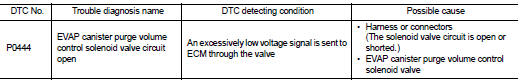
DTC CONFIRMATION PROCEDURE
1.CONDITIONING
If DTC Confirmation Procedure has been previously conducted, always turn ignition switch OFF and wait at least 10 seconds before conducting the next test.
TESTING CONDITION:
Before performing the following procedure, confirm battery voltage is more than
11 V at id
le.
>> GO TO 2.
2.PERFORM DTC CONFIRMATION PROCEDURE
1. Start engine and let it idle for at least 13 seconds.
2. Check 1st trip DTC.
Is 1st trip DTC detected? YES >> Go to EC-669, "Diagnosis Procedure".
NO >> INSPECTION END
Diagnosis Procedure
1.CHECK EVAP CANISTER PURGE VOLUME CONTROL SOLENOID VALVE POWER SUPPLY CIRCUIT
1. Turn ignition switch OFF.
2. Disconnect EVAP canister purge volume control solenoid valve harness connector.
3. Turn ignition switch ON.
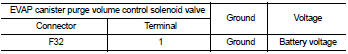
4. Check the voltage between EVAP canister purge volume control solenoid valve harness connector and ground.
Is the inspection result normal? YES >> GO TO 3.
NO >> GO TO 2.
2.DETECT MALFUNCTIONING PART
Check the following.
• Harness for open or short between EVAP canister purge volume control solenoid
valve and IPDM E/R
• Harness for open or short between EVAP canister purge volume control solenoid
valve and ECM
>> Repair open circuit or short to ground or short to power in harness or
connectors.
3.CHECK EVAP CANISTER PURGE VOLUME CONTROL SOLENOID VALVE OUTPUT SIGNAL CIRCUIT FOR OPEN AND SHORT
1. Turn ignition switch OFF.
2. Disconnect ECM harness connector.
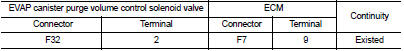
3. Check the continuity between EVAP canister purge volume control solenoid valve harness connector and ECM harness connector.
4. Also check harness for short to ground and short to power.
Is the inspection result normal? YES-1 >> With CONSULT-III: GO TO 4.
YES-2 >> Without CONSULT-III: GO TO 5.
NO >> Repair open circuit or short to ground or short to power in harness or connectors.
4.CHECK EVAP CANISTER PURGE VOLUME CONTROL SOLENOID VALVE OPERATION
 With CONSULT-III
1. Reconnect all harness connectors disconnected.
2. Start engine.
3. Perform “PURG VOL CONT/V” in “ACTIVE TEST” mode with CONSULT-III. Check that engine speed varies according to the valve opening.
Does engine speed vary according to the valve opening? YES >> GO TO 6.
NO >> GO TO 5.
5.CHECK EVAP CANISTER PURGE VOLUME CONTROL SOLENOID VALVE
Refer to EC-670, "Component Inspection".
Is the inspection result normal? YES >> GO TO 6.
NO >> Replace EVAP canister purge volume control solenoid valve.
6.CHECK INTERMITTENT INCIDENT
Refer to GI-42, "Intermittent Incident".
>> INSPECTION END
Component Inspection
1.CHECK EVAP CANISTER PURGE VOLUME CONTROL SOLENOID VALVE
 With CONSULT-III
1. Turn ignition switch OFF.
2. Reconnect all harness connectors disconnected.
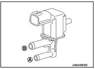
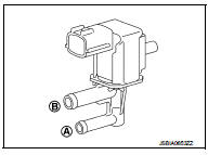
3. Disconnect EVAP purge hoses connected to EVAP canister purge volume control solenoid valve.
4. Turn ignition switch ON.
5. Select “PURG VOL CONT/V” in “ACTIVE TEST” mode with CONSULT-III.
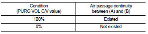
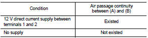
6. Touch “Qd” and “Qu” on CONSULT-III screen to adjust “PURG VOL C/V” opening and check air passage continuity of EVAP canister purge volume control solenoid valve under the following conditions.
 Without CONSULT-III
1. Turn ignition switch OFF.
2. Disconnect EVAP canister purge volume control solenoid valve harness connector.
3. Disconnect EVAP purge hoses connected to EVAP canister purge volume control solenoid valve.
4. Check air passage continuity of EVAP canister purge volume control solenoid valve under the following conditions.
Is the inspection result normal? YES >> INSPECTION END
NO >> Replace EVAP canister purge volume control solenoid valve
 P0420 three way catalyst function
DTC Logic
DTC DETECTION LOGIC
The ECM monitors the switching frequency ratio of air fuel ratio (A/F)
sensor 1 and heated oxygen sensor 2.
A three way catalyst (manifold) with high oxygen storage ...
 P0500 VSS
Description
The vehicle speed signal is sent to the combination meter from the “ABS
actuator and electric unit (control
unit)” by CAN communication line. The combination meter then sends a sig ...
Other materials:
B2602 shift position
DTC Logic
DTC DETECTION LOGIC
NOTE:
• If DTC B2602 is displayed with DTC U1000, first perform the trouble diagnosis
for DTC U1000. Refer to
BCS-83, "DTC Logic".
• If DTC B2602 is displayed with DTC U1010, first perform the trouble diagnosis
for DTC U1010. Refer to
BCS-84, &qu ...
Precaution for Supplemental Restraint System (SRS) "AIR BAG" and "SEAT BELT
PRE-TENSIONER"
The Supplemental Restraint System such as “AIR BAG” and “SEAT BELT PRE-TENSIONER”,
used along
with a front seat belt, helps to reduce the risk or severity of injury to the
driver and front passenger for certain
types of collision. This system includes seat belt switch inputs and dual s ...
Interior lights
The interior illumination system can be set to manually turn on via switch position 1, allowing the cabin lights to remain lit regardless of whether the doors are open or closed. To conserve energy, these lights will automatically go off after a predetermined period of time unl ...
