Nissan Juke Service and Repair Manual : System
System Description
Fan speed of blower motor is changed by the combination of fan control dial (fan switch) operation and blower fan resistor control.
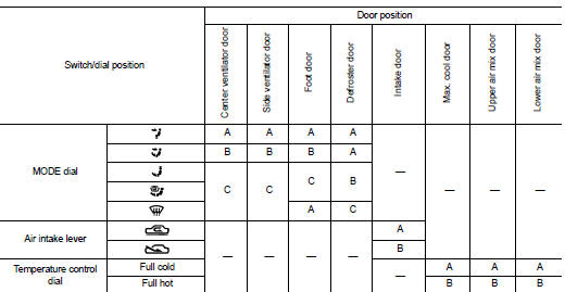
Door Control
SWITCHES AND THEIR CONTROL FUNCTIONS
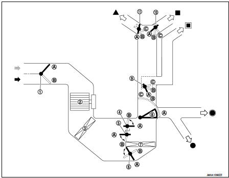
1. Intake door
2. Blower motor
3. Air conditioner filter
4. Max. cool door
5. Upper air mix door
6. Lower air mix door
7. Heater core
8. Foot door
9. Side ventilator door
10. Center ventilator door
11. Defroster door
 Fresh air intake
 Recirculation air
 Defroster
 Center ventilator
 Side ventilator
 Foot
Foot
 Rear foot*
*: With rear foot duct
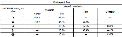
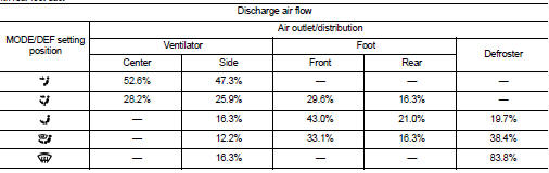
AIR DISTRIBUTION
Without rear foot duct
With rear foot duct
 Component parts
Component Part Location
1. BCM
Refer to BCS-161, "Removal and Installation".
2. Heater control
3. Blower fan resistor
4. Blower motor
A. Left side of heater unit assembly
B. Right ...
 Operation
Switch Name and Function
HEATER CONTROLLER (HEATER CONTROL)
1. MODE dial
2. Fan control dial
3. Temperature control dial
4. Intake lever
...
Other materials:
A/C unit assembly
Exploded View (Automatic Air Conditioning)
REMOVAL
LHD models (4WD)
1. A/C unit assembly
2. Drain hose
3. Steering member
4. Instrument stay
: Clip
: N·m (kg-m, ft-lb)
DISASSEMBLY
LHD models (4WD)
1. Ventilator seal
2. Defroster seal
3. Upper attachment case
4. Sub defroster d ...
Rear window and outside mirror defroster switch
Type A
Type B
To defog/defrost the rear window glass and outside mirrors (if so equipped),
start the engine and push the switch 1 on. The indicator light 2 will illuminate.
Push the switch again to turn the defroster off.
It will automatically turn off in approximately 15 minutes.
CAUTIO ...
Wiring diagram
DOOR & LOCK SYSTEM
Wiring Diagram
For connector terminal arrangements, harness layouts, and alphabets in a
(option abbreviation; if not
described in wiring diagram), refer to GI-12, "Connector Information/Explanation
of Option Abbreviation".
...
