Nissan Juke Service and Repair Manual : P0335 CKP sensor (POS)
DTC Logic
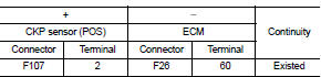
DTC DETECTION LOGIC
NOTE
:
If DTC P0340 is displayed with DTC P0643, first perform the trouble diagnosis
for DTC P0643.
Refer to EC-307, "DTC Logic".
DTC CONFIRMATION PROCEDURE
1.PRECONDITIONING
If DTC Confirmation Procedure has been previously conducted, always perform the following procedure before conducting the next test.
1. Turn ignition switch OFF and wait at least 10 seconds.
2. Turn ignition switch ON.
3. Turn ignition switch OFF and wait at least 10 seconds.
TESTING CONDITION:
Before performing the following procedure, confirm that battery voltage is more
than 10.5 V with ignition
switch ON.
>> GO TO 2.
2.PERFORM DTC CONFIRMATION PROCEDURE
1. Start engine and let it idle for at least 5 seconds.
If engine does not start, crank engine for at least 2 seconds.
2. Check 1st trip DTC.
Is 1st trip DTC detected? YES >> Proceed to EC-271, "Diagnosis Procedure".
NO >> INSPECTION END
Diagnosis Procedure
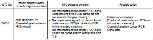
1.CHECK CRANKSHAFT POSITION (CKP) SENSOR (POS) POWER SUPPLY
1. Disconnect crankshaft position (CKP) sensor (POS) harness connector.
2. Turn ignition switch ON.
3. Check the voltage between CKP sensor (POS) harness connector and ground.
Is the inspection result normal? YES >> GO TO 3.
NO >> GO TO 2.
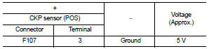
2.CHECK CKP SENSOR (POS) POWER SUPPLY CIRCUIT
1. Turn ignition switch OFF 2. Disconnect ECM harness connector.
3. Check the continuity between CKP sensor (POS) harness connector and ECM harness connector.
4. Also check harness for short to ground.
Is the inspection result normal? YES >> Perform the trouble diagnosis for power supply circuit.
NO >> Repair or replace error-detected parts.
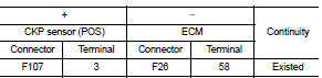
3.CHECK CKP SENSOR (POS) GROUND CIRCUIT
1. Turn ignition switch OFF.
2. Disconnect ECM harness connector.
3. Check the continuity between CKP sensor (POS) harness connector and ECM harness connector.
4. Also check harness for short to power.
Is the inspection result normal? YES >> GO TO 4.
NO >> Repair or replace error-detected parts.
4.CHECK CKP SENSOR (POS) INPUT SIGNAL CIRCUIT
1. Check the continuity between CKP sensor (POS) harness connector and ECM harness connector.
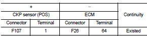
2. Also check harness for short to ground and to power.
Is the inspection result normal? YES >> GO TO 5.
NO >> Repair or replace error-detected parts.
5.CHECK CRANKSHAFT POSITION SENSOR (POS)
Check the crankshaft position sensor (POS). Refer to EC-273, "Component Inspection".
Is the inspection result normal? YES >> GO TO 6.
NO >> Replace crankshaft position sensor (POS). Refer to EM-103, "Exploded View".
6.CHECK GEAR TOOTH
1. Remove crankshaft position sensor (POS). Refer to EM-103, "Exploded View".
2. Look into the mounting hole (A) of the crankshaft position sensor (POS) to check that there is no missing gear tooth in the signal plate (1).
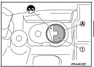
Is the inspection result normal? YES >> Check intermittent incident. Refer to GI-42, "Intermittent Incident".
NO >> Replace the signal plate. Refer to EM-103, "Exploded View".
Component Inspection
1.CHECK CRANKSHAFT POSITION SENSOR (POS)-I
1. Turn ignition switch OFF.
2. Loosen the fixing bolt of the sensor.
3. Disconnect crankshaft position sensor (POS) harness connector.
4. Remove the sensor.
5. Visually check the sensor for chipping.
Is the inspection result normal? YES >> GO TO 2.
NO >> Replace crankshaft position sensor (POS). Refer to EM- 103, "Exploded View".
2.CHECK CRANKSHAFT POSITION SENSOR (POS)-II
Check the resistance between crankshaft position sensor (POS) terminals as per the following.
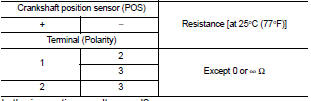
Is the inspection result normal? YES >> INSPECTION END NO >> Replace crankshaft position sensor (POS). Refer to EM-103, "Exploded View".
 P0327, P0328 KS
DTC Logic
DTC DETECTION LOGIC
DTC CONFIRMATION PROCEDURE
1.PRECONDITIONING
If DTC Confirmation Procedure has been previously conducted, always perform
the following procedure
before conductin ...
 P0340 CMP sensor (PHASE)
DTC Logic
DTC DETECTION LOGIC
DTC CONFIRMATION PROCEDURE
1.PRECONDITIONING
If DTC Confirmation Procedure has been previously conducted, always perform
the following procedure
before conductin ...
Other materials:
Car phone or CB radio
When installing a car phone or a CB radio in your vehicle, be sure to observe
the following precautions, otherwise the new equipment may adversely affect the
electronic control modules and electronic control system harness.
WARNING
• A cellular phone should not be used for any purpose ...
System
AUTO RETRACTABLE DOOR MIRORR FUNCTION
AUTO RETRACTABLE DOOR MIRORR FUNCTION : System Diagram
AUTO RETRACTABLE DOOR MIRORR FUNCTION : System Description
BCM retracts door mirror when door lock signal is received from Intelligent
Key or door request switch.
OPERATION CONDITION
The system oper ...
Precautions on child restraints
WARNING
• Failure to follow the warnings and instructions for proper use and installation
of child restraints could result in serious injury or death of a child or other
passengers in a sudden stop or collision:
— The child restraint must be used and installed properly. Always follow all o ...
