Nissan Juke Service and Repair Manual : P0340 CMP sensor (PHASE)
DTC Logic
DTC DETECTION LOGIC
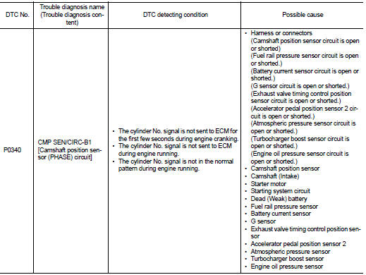
DTC CONFIRMATION PROCEDURE
1.PRECONDITIONING
If DTC Confirmation Procedure has been previously conducted, always perform the following procedure before conducting the next test.
1. Turn ignition switch OFF and wait at least 10 seconds.
2. Turn ignition switch ON.
3. Turn ignition switch OFF and wait at least 10 seconds.
TESTING CONDITION:
Before performing the following procedure, confirm that battery voltage is more
than 10.5 V with ignition
switch ON.
>> GO TO 2.
2.PERFORM DTC CONFIRMATION PROCEDURE-I
1. Start engine and let it idle for at least 5 seconds.
If engine does not start, crank engine for at least 2 seconds.
2. Check 1st trip DTC.
Is 1st trip DTC detected? YES >> Proceed to EC-275, "Diagnosis Procedure".
NO >> GO TO 3.
3.PERFORM DTC CONFIRMATION PROCEDURE-I
1. Maintaining engine speed at more than 800 rpm for at least 5 seconds.
2. Check 1st trip DTC.
Is 1st trip DTC detected? YES >> Proceed to EC-275, "Diagnosis Procedure".
NO >> INSPECTION END
Diagnosis Procedure
1.CHECK STARTING SYSTEM
Turn ignition switch to START position.
Does the engine turn over? Does the starter motor operate? YES >> GO TO 2.
NO >> Check starting system (Refer to EC-124, "Work Flow".).
2.CHECK CAMSHAFT POSITION (CMP) SENSOR (PHASE) POWER SUPPLY
1. Turn ignition switch OFF.
2. Disconnect camshaft position (CMP) sensor (PHASE) harness connector.
3. Turn ignition switch ON.
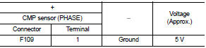
4. Check the voltage between CMP sensor (PHASE) harness connector and ground.
Is the inspection result normal? YES >> GO TO 4.
NO >> GO TO 3.
3.CHECK SENSOR POWER SUPPLY CIRCUIT
1. Turn ignition switch OFF.
2. Disconnect ECM harness connector.
3. Check harness connector for short to power and short to ground, between the following terminals.
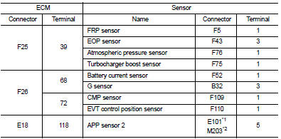
*1: LHD models or RHD with CVT models *2: RHD with M/T models
Is inspection result normal? YES >> Perform the trouble diagnosis for power supply circuit.
NO >> Repair or replace error-detected parts.
4.CHECK CMP SENSOR (PHASE) GROUND CIRCUIT
1. Turn ignition switch OFF.
2. Disconnect ECM harness connector.
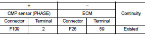
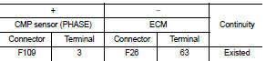
3. Check the continuity between CMP sensor (PHASE) harness connector and ECM harness connector.
4. Also check harness for short to power.
Is the inspection result normal? YES >> GO TO 5.
NO >> Repair or replace error-detected parts.
5.CHECK CMP SENSOR (PHASE) INPUT SIGNAL CIRCUIT
1. Disconnect ECM harness connector.
2. Check the continuity between CMP sensor (PHASE) harness connector and ECM harness connector.
3. Also check harness for short to ground and to power.
Is the inspection result normal? YES >> GO TO 6.
NO >> Repair or replace error-detected parts.
6.CHECK CAMSHAFT POSITION SENSOR (PHASE)
Check the camshaft position sensor (PHASE). Refer to EC-276, "Component Inspection".
Is the inspection result normal? YES >> GO TO 7.
NO >> Replace camshaft position sensor (PHASE). Refer to EM-79, "Removal and Installation".
7.CHECK CAMSHAFT (INT)
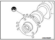
Check the following.
• Accumulation of debris to the signal plate of camshaft rear end • Chipping signal plate of camshaft rear end
Is the inspection result normal? YES >> Check intermittent incident. Refer to GI-42, "Intermittent Incident".
NO >> Remove debris and clean the signal plate of camshaft rear end or replace camshaft. Refer to EM-79, "Removal and Installation".
Component Inspection
1.CHECK CAMSHAFT POSITION SENSOR (PHASE)-I
1. Turn ignition switch OFF.
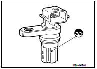
2. Loosen the fixing bolt of the sensor.
3. Disconnect camshaft position sensor (PHASE) harness connector.
4. Remove the sensor.
5. Visually check the sensor for chipping.
Is the inspection result normal? YES >> GO TO 2.
NO >> Replace camshaft position sensor (PHASE).
2.CHECK CAMSHAFT POSITION SENSOR (PHASE)-II
Check the resistance camshaft position sensor (PHASE) terminals as per the following.
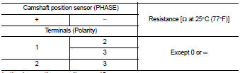
Is the inspection result normal? YES >> INSPECTION END
NO >> Replace camshaft position sensor (PHASE). Refer to EM-79, "Removal and Installation".
 P0335 CKP sensor (POS)
DTC Logic
DTC DETECTION LOGIC
NOTE:
If DTC P0340 is displayed with DTC P0643, first perform the trouble diagnosis
for DTC P0643.
Refer to EC-307, "DTC Logic".
DTC CONFIRMATION PRO ...
 P0420 three way catalyst function
DTC Logic
DTC DETECTION LOGIC
The ECM monitors the switching frequency ratio of air fuel ratio (A/F)
sensor 1 and heated oxygen sensor 2.
A three way catalyst (manifold) with high oxygen storage ...
Other materials:
Malfunction indicator
Component Function Check
1.CHECK MI FUNCTION
1. Turn ignition switch ON.
2. Make sure that MI lights up.
Is the inspection result normal?
YES >> INSPECTION END
NO >> Go to EC-1019, "Diagnosis Procedure".
Diagnosis Procedure
1.CHECK CAN COMMUNICATION LINE
Refer to LAN ...
Types of tires
WARNING
When selecting replacement tires for your Nissan Leaf, it is mandatory to ensure all four tires are of the identical type (e.g., Summer, All-Season, or Snow) and construction. A NISSAN certified LEAF dealer can provide expert guidance regarding the correct tire type, size, spe ...
Control valve
Exploded View
COMPONENT PARTS LOCATION
1. Transaxle assembly
2. Control valve
3. Bracket
4. O-ring
5. Oil strainer assembly
6. Magnet
7. Drain plug gasket
8. Drain plug
9. Oil pan mounting bolt
10. Oil pan
11. Oil pan gasket
12. Lock nut
13. Washer
14. Manual plate
15. Co ...
