Nissan Juke Service and Repair Manual : P0180 FPT sensor
DTC Logic
DTC DETECTION LOGIC
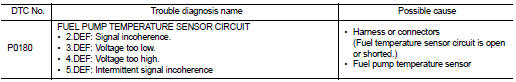
Diagnosis Procedure
1.CHECK GROUND CONNECTIONS
1. Turn ignition switch OFF.
2. Check ground connection E38. Refer to Ground inspection in GI-44, "Circuit Inspection".
Is the inspection result normal? YES >> GO TO 2.
NO >> Repair or replace ground connection.
2.CHECK FUEL TEMPERATURE SENSOR SUPPLY CIRCUIT
1. Disconnect fuel temperature sensor harness connector.
2. Turn ignition switch ON.
3. Check the voltage between fuel temperature sensor connector and ground.
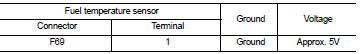
Is the inspection result normal? YES >> GO TO 3.
NO >> Repair open circuit or short to ground or short to power in harness or connectors.
3.CHECK FUEL TEMPERATURE SENSOR GROUND CIRCUIT FOR OPEN AND SHORT
1. Turn ignition switch OFF.
2. Disconnect ECM harness connector.
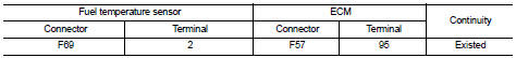
3. Check the continuity between fuel temperature sensor harness connector and ECM harness connector.
4. Also check harness for short to ground and short to power.
Is the inspection result normal? YES >> GO TO 4.
NO >> Repair open circuit or short to ground or short to power in harness or connectors.
4.CHECK FUEL TEMPERATURE SENSOR
Refer to EC-916, "Component Inspection".
Is the inspection result normal? YES >> GO TO 5.
NO >> Replace fuel temperature sensor.
5.CHECK INTERMITTENT INCIDENT
Refer to GI-42, "Intermittent Incident", ???INCIDENT SIMULATION TESTS??? and ???GROUND INSPECTION???.
>> INSPECTION END
Component Inspection
1.CHECK FUEL TEMPERATURE SENSOR
Check resistance between fuel temperature sensor terminals 1 and 2 under the following conditions.
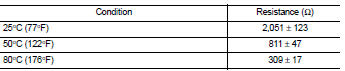
Is the inspection result normal? YES >> INSPECTION END
NO >> Replace fuel temperature sensor.
 P012B TC boost sensor
DTC Logic
DTC DETECTION LOGIC
Diagnosis Procedure
1.CHECK GROUND CONNECTIONS
1. Turn ignition switch OFF.
2. Check ground connection E38. Refer to Ground inspection in GI-44, "Circuit
In ...
 P0190 FRP sensor
DTC Logic
DTC DETECTION LOGIC
Diagnosis Procedure
1.CHECK GROUND CONNECTIONS
1. Turn ignition switch OFF.
2. Check ground connection E38. Refer to Ground inspection in GI-44, "Circuit
In ...
Other materials:
Lights
Headlight assembly
Map light
Room light
High-mounted stop light
Rear combination light
Door mirror turn signal light (if so equipped)
Cargo light
License plate light
Fog light (if so equipped)
...
Heated steering wheel switch
The Nissan Leaf heated steering wheel system is designed with intelligent efficiency, operating only when the surface temperature of the steering wheel is below approximately 68ÂşF (20ÂşC).
To activate the system, push the heated steering wheel switch while the p ...
U1000 can comm circuit
Description
CAN (Controller Area Network) is a serial communication system for real time
application. It is an on-vehicle
multiplex communication system with high data communication speed and excellent
error detection ability.
Many electronic control units are equipped onto vehicles, and ea ...
