Nissan Juke Service and Repair Manual : P012B TC boost sensor
DTC Logic
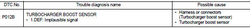
DTC DETECTION LOGIC
Diagnosis Procedure
1.CHECK GROUND CONNECTIONS
1. Turn ignition switch OFF.
2. Check ground connection E38. Refer to Ground inspection in GI-44, "Circuit Inspection".
Is the inspection result normal? YES >> GO TO 2.
NO >> Repair or replace ground connection.
2.CHECK TUBOCHARGER BOOST SENSOR SUPPLY CIRCUIT
1. Disconnect turbocharger boost sensor harness connector.
2. Turn ignition switch ON.
3. Check the voltage between turbocharger boost sensor connector and ground.
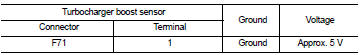
Is the inspection result normal? YES >> GO TO 3.
NO >> Repair open circuit or short to ground or short to power in harness or connectors.
3.CHECK TUBOCHARGER BOOST SENSOR GROUND CIRCUIT FOR OPEN AND
SHORT
1. Turn ignition switch OFF.
2. Disconnect ECM harness connector.
3. Check the continuity between turbocharger boost sensor harness connector and ECM harness connector.
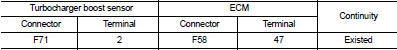
4. Also check harness for short to ground and short to power.
Is the inspection result normal? YES >> GO TO 4.
NO >> Repair open circuit or short to ground or short to power in harness or connectors.
4.CHECK TUBOCHARGER BOOST SENSOR INPUT SIGNAL CIRCUIT FOR OPEN AND SHORT
1. Check the continuity between turbocharger boost sensor harness connector and ECM harness connector.
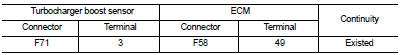
2. Also check harness for short to ground and short to power.
Is the inspection result normal?
YES >> GO TO 5.
NO >> Repair open circuit or short to ground or short to power in harness or connectors.
5.CHECK TUBOCHARGER BOOST SENSOR
Refer to EC-914, "Component Inspection".
Is the inspection result normal? YES >> GO TO 6.
NO >> Replace turbocharger boost sensor.
6.REPLACE ECM
1. Perform EC-879, "Work Procedure".
2. Perform EGR volume control valve closed position learning. Refer to EC-881, "Work Procedure".
>> INSPECTION END
Component Inspection
1.CHECK TURBOCHARGER BOOST SENSOR-I
1. Turn ignition switch OFF.
2. Remove turbocharger boost sensor with its harness connected.
3. Turn ignition switch ON.
4. Select ???DATA MONITOR??? mode with CONSULT-III.
5. Check ???BOOST PRESS??? and ???ATOMOS PRESS??? indication.
If the value is not very close to ???ATOMOS PRESS???, maximum pressure difference between ???ATOMOS PRESS??? and ???BOOST PRESS??? with the ignition switch ON (engine stop) = ?┬▒ 50 mbar? YES >> GO TO 2.
NO >> Replace turbocharger boost sensor.
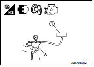
2.CHECK TURBOCHARGER BOOST SENSOR-II
1. Use pump (A) to apply turbocharger boost sensor (1) as shown in the figure.
2. Apply a pressure of between 10 kPa (0.100 bar, 0.102 kg/cm2, 1.5 psi) - 13 kPa (0.130 bar, 0.133 kg/cm2, 1.9 psi) [maximum pressure to be applied: 13 kPa (0.130 bar, 0.133 kg/cm2, 1.9 psi)].
3. Select ???DATA MONITOR??? mode with CONSULT-III.
4. Check ???BOOST PRESS??? indication with that given by the vacuum pump.
If there is no discrepancy? YES >> INSPECTION END
NO >> Replace turbocharger boost sensor.
 P012A TC boost sensor
DTC Logic
DTC DETECTION LOGIC
Diagnosis Procedure
1.CHECK GROUND CONNECTIONS
1. Turn ignition switch OFF.
2. Check ground connection E38. Refer to Ground inspection in GI-44, "Circuit
In ...
 P0180 FPT sensor
DTC Logic
DTC DETECTION LOGIC
Diagnosis Procedure
1.CHECK GROUND CONNECTIONS
1. Turn ignition switch OFF.
2. Check ground connection E38. Refer to Ground inspection in GI-44, "Circuit
In ...
Other materials:
Idle air volume learning
Description
Idle Air Volume Learning is a function of ECM to learn the idle air volume
that keeps each engine idle speed
within the specific range. It must be performed under any of the following
conditions:
ÔÇó Each time electric throttle control actuator or ECM is replaced.
ÔÇó Idle speed ...
Difference between predictive and actual distances
Backing up on a steep uphill
When backing up the vehicle up a hill, the distance guide lines and the vehicle
width guide lines are shown closer than the actual distance.
For example, the display shows 3 ft (1 m) to the placeA , but the actual 3 ft
(1 m) distance on the hill is the placeB . N ...
Sample/Wiring Diagram -Example-
Each section includes wiring diagrams.
Description
SWITCH POSITIONS
Switches are shown in wiring diagrams as if the vehicle is in the ÔÇťnormalÔÇŁ
condition.
A vehicle is in the ÔÇťnormalÔÇŁ condition when:
ÔÇó ignition switch is ÔÇťOFFÔÇŁ,
ÔÇó doors, hood and trunk lid/back door are ...
