Nissan Juke Service and Repair Manual : P012A TC boost sensor
DTC Logic
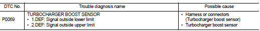
DTC DETECTION LOGIC
Diagnosis Procedure
1.CHECK GROUND CONNECTIONS
1. Turn ignition switch OFF.
2. Check ground connection E38. Refer to Ground inspection in GI-44, "Circuit Inspection".
Is the inspection result normal? YES >> GO TO 2.
NO >> Repair or replace ground connection.
2.CHECK TUBOCHARGER BOOST SENSOR SUPPLY CIRCUIT
1. Disconnect turbocharger boost sensor harness connector.
2. Turn ignition switch ON.
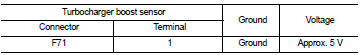
3. Check the voltage between turbocharger boost sensor connector and ground.
Is the inspection result normal? YES >> GO TO 3.
NO >> Repair open circuit or short to ground or short to power in harness or connectors.
3.CHECK TUBOCHARGER BOOST SENSOR GROUND CIRCUIT FOR OPEN AND SHORT
1. Turn ignition switch OFF.
2. Disconnect ECM harness connector.
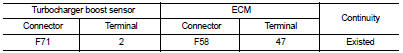
3. Check the continuity between turbocharger boost sensor harness connector and ECM harness connector
4. Also check harness for short to ground and short to power.
Is the inspection result normal? YES >> GO TO 4.
NO >> Repair open circuit or short to ground or short to power in harness or connectors.
4.CHECK TUBOCHARGER BOOST SENSOR INPUT SIGNAL CIRCUIT FOR OPEN AND SHORT
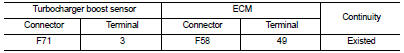
1. Check the continuity between turbocharger boost sensor harness connector and ECM harness connector.
2. Also check harness for short to ground and short to power.
Is the inspection result normal?
YES >> GO TO 5.
NO >> Repair open circuit or short to ground or short to power in harness or connectors.
5.CHECK TUBOCHARGER BOOST SENSOR
Refer to EC-912, "Component Inspection".
Is the inspection result normal? YES >> GO TO 6.
NO >> Replace turbocharger boost sensor.
6.REPLACE ECM
1. Perform EC-879, "Work Procedure".
2. Perform EGR volume control valve closed position learning. Refer to EC-881, "Work Procedure".
>> INSPECTION END
Component Inspection
1.CHECK TURBOCHARGER BOOST SENSOR-I
1. Turn ignition switch OFF.
2. Remove turbocharger boost sensor with its harness connected.
3. Turn ignition switch ON.
4. Select ???DATA MONITOR??? mode with CONSULT-III.
5. Check ???BOOST PRESS??? and ???ATOMOS PRESS??? indication.
If the value is not very close to ???ATOMOS PRESS???, maximum pressure difference between ???ATOMOS PRESS??? and ???BOOST PRESS??? with the ignition switch ON (engine stop) = ?± 50 mbar? YES >> GO TO 2.
NO >> Replace turbocharger boost sensor.
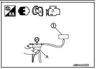
2.CHECK TURBOCHARGER BOOST SENSOR-II
1. Use pump (A) to apply turbocharger boost sensor (1) as shown in the figure.
2. Apply a pressure of between 10 kPa (0.100 bar, 0.102 kg/cm2, 1.5 psi) - 13 kPa (0.130 bar, 0.133 kg/cm2, 1.9 psi) [maximum pressure to be applied: 13 kPa (0.130 bar, 0.133 kg/cm2, 1.9 psi)].
3. Select ???DATA MONITOR??? mode with CONSULT-III.
4. Check ???BOOST PRESS??? indication with that given by the vacuum pump.
If there is no discrepancy? YES >> INSPECTION END
NO >> Replace turbocharger boost sensor.
 P0120 TP sensor
DTC Logic
DTC DETECTION LOGIC
Diagnosis Procedure
1.CHECK GROUND CONNECTIONS
1. Turn ignition switch OFF and wait at least 20 seconds.
2. Check ground connection E38. Refer to Ground inspection ...
 P012B TC boost sensor
DTC Logic
DTC DETECTION LOGIC
Diagnosis Procedure
1.CHECK GROUND CONNECTIONS
1. Turn ignition switch OFF.
2. Check ground connection E38. Refer to Ground inspection in GI-44, "Circuit
In ...
Other materials:
Small children
Children that are over 1 year old and weigh at least 20 lbs (9 kg) should remain
in a rear-facing child restraint as long as possible up to the height or weight
limit of the child restraint.
Children who outgrow the height or weight limit of the rear-facing child restraint
and are at least 1 ...
Washer tank
Exploded View
1. Front washer nozzle LH
2. Front washer nozzle RH
3. Front washer tube LH
4. Front washer tube RH
5. Check valve
6. Front washer tube
7. Joint
8. Washer tank inlet cap
9. Washer tank inlet
10. Washer tank
11. Headlamp washer pump
12. Washer pump
13. Packing
1 ...
RAB system operation
RAB warning light and dedicated system warning indicator
Steering-wheel-mounted control switches (located on the left side)
Center infotainment and information display
The RAB system is active whenever the shift lever is placed in the R (R ...
