Nissan Juke Service and Repair Manual : Operation
Switch Name and Function
A/C CONTROLLER (A/C CONTROL)
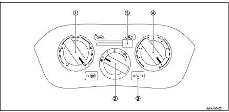
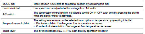
1. MODE dial
2. Fan control dial
3. A/C switch
4. Temperature control dial
5. Intake lever
 System
System Diagram
System Description
DESCRIPTION
• Manual air conditioning system is controlled by each function of thermo
control amp., BCM, ECM and IPDM
E/R.
• Fan speed of blower motor is ...
 Diagnosis system (BCM) (with intelligent key system)
Description
Air conditioning system performs self-diagnosis, operation check, function
diagnosis, and various settings
using diagnosis function of each control unit.
Common item : consult-III F ...
Other materials:
Structure and operation
Sectional View
1. 5th input gear
2. 5th-reverse synchronizer hub assembly
3. Input shaft
4. Mainshaft
5. 5th main gear
6. Mainshaft rear bearing
7. 4th main gear
8. 3rd-4th synchronizer hub assembly
9. 3rd main gear
10. 2nd main gear
11. 1st-2nd synchronizer hub assembly
12. Dif ...
Cleaning interior
Occasionally remove loose dust from the interior trim, plastic parts and seats
using a vacuum cleaner or soft bristled brush. Wipe the vinyl and leather surfaces
with a clean, soft cloth dampened in mild soap solution, then wipe clean with a
dry soft cloth.
Regular care and cleaning is requir ...
P0657 ECM relay
DTC Logic
DTC DETECTION LOGIC
NOTE:
When IPDM E/R DTC is indicated with DTC P0657, IPDM E/R DTC must be checked
first.
Diagnosis Procedure
1.CHECK GROUND CONNECTION
1. Turn ignition switch OFF.
2. Check ground connection E38. Refer to Ground Inspection in GI-44, "Circuit
Inspection ...
