Nissan Juke Service and Repair Manual : Diagnosis system (BCM) (with intelligent key system)
Description
Air conditioning system performs self-diagnosis, operation check, function diagnosis, and various settings using diagnosis function of each control unit.

Common item : consult-III Function (BCM - COMMON ITEM)
APPLICATION ITEM
CONSULT-III performs the following functions via CAN communication with BCM.

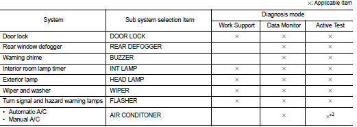
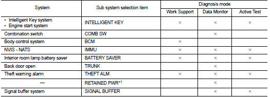
SYSTEM APPLICATION
BCM can perform the following functions for each system.
NOTE
:
It can perform the diagnosis modes except the following for all sub system
selection items.


NOTE
:
• *1: This item is displayed, but not used.
• *2: For models with automatic A/C, this diagnosis mode is not used.
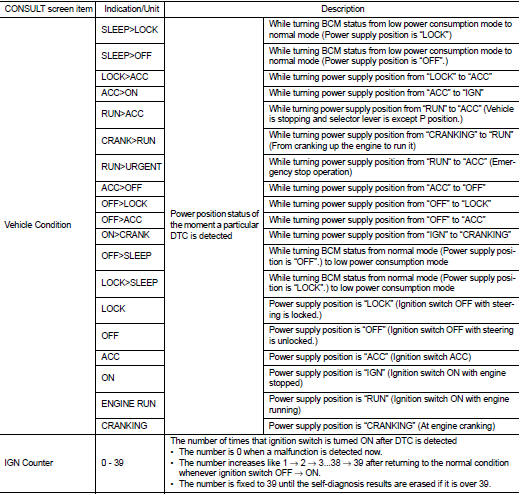
FREEZE FRAME DATA (FFD)
The BCM records the following vehicle condition at the time a particular DTC is detected, and displays on CONSULT-III.


Air conditioner : consult-III Function (BCM - AIR CONDITIONER) (Manual A/ C 4WD Models)
DATA MONITOR
Display item list

ACTIVE TEST

 Operation
Switch Name and Function
A/C CONTROLLER (A/C CONTROL)
1. MODE dial
2. Fan control dial
3. A/C switch
4. Temperature control dial
5. Intake lever
...
 Diagnosis system (BCM) (without intelligent key system)
Description
Air conditioning system performs self-diagnosis, operation check, function
diagnosis, and various settings
using diagnosis function of each control unit.
Common item : consult-III F ...
Other materials:
Insufficient cooling
Description
Symptom
• Insufficient cooling
• No cool air comes out. (Air flow volume is normal.)
Diagnosis Procedure
NOTE:
Perform self-diagnoses with CONSULT-III before performing symptom diagnosis. If
any DTC is detected, perform
the corresponding diagnosis.
1.CHECK MAGNET CLUTCH OPERA ...
RearView monitor (if so equipped)
When the shift lever is shifted into the R (Reverse) position, the monitor display
shows the view to the rear of the vehicle.
The system is designed as an aid to the driver in situations such as slot parking
or parallel parking.
WARNING
Failure to follow the warnings and instructions for prop ...
Precaution for Liquid Gasket
REMOVAL OF LIQUID GASKET
• After removing the mounting bolts and nuts, separate the mating
surface using a seal cutter and remove the liquid gasket.
CAUTION:
Be careful not to damage the mating surfaces.
• In areas where the cutter is difficult to use, use a plastic hammer to
lightly tap the ...
