
Nissan Juke Service and Repair Manual : P0605 ECM
DTC Logic
DTC DETECTION LOGIC
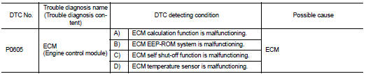
DTC CONFIRMATION PROCEDURE
1.PRECONDITIONING
If DTC Confirmation Procedure has been previously conducted, always perform the following procedure before conducting the next test.
1. Turn ignition switch OFF and wait at least 10 seconds.
2. Turn ignition switch ON.
3. Turn ignition switch OFF and wait at least 10 seconds.
>> GO TO 2.
2.PERFORM DTC CONFIRMATION PROCEDURE FOR MALFUNCTION A
1. Turn ignition switch ON.
2. Check 1st trip DTC.
Is 1st trip DTC detected? YES >> Proceed to EC-302, "Diagnosis Procedure".
NO >> GO TO 3.
3.PERFORM DTC CONFIRMATION PROCEDURE FOR MALFUNCTION B
1. Turn ignition switch ON and wait at least 1 second.
2. Turn ignition switch OFF, wait at least 10 seconds and then turn ON.
3. Check 1st trip DTC.
Is 1st trip DTC detected? YES >> Proceed to EC-302, "Diagnosis Procedure".
NO >> GO TO 4.
4.PERFORM DTC CONFIRMATION PROCEDURE FOR MALFUNCTION C
1. Turn ignition switch ON and wait at least 1 second.
2. Turn ignition switch OFF, wait at least 10 seconds and then turn ON.
3. Repeat step 2 for 32 times.
4. Check 1st trip DTC.
Is 1st trip DTC detected? YES >> Proceed to EC-302, "Diagnosis Procedure".
NO >> INSPECTION END
Diagnosis Procedur
1.INSPECTION START
1. Turn ignition switch ON.
2. Erase DTC.
3. Perform DTC confirmation procedure. Refer to EC-302, "DTC Logic".
Is the 1st trip DTC P0605 displayed again?
YES >> Replace ECM. Refer to EC-447, "Removal and Installation".
NO >> INSPECTION END
 P0603 ECM power supply
DTC Logic
DTC DETECTION LOGIC
DTC CONFIRMATION PROCEDURE
1.PRECONDITIONING
If DTC Confirmation Procedure has been previously conducted, always perform
the following procedure
before conductin ...
 P0607 ECM
DTC Logic
DTC DETECTION LOGIC
DTC CONFIRMATION PROCEDURE
1.PERFORM DTC CONFIRMATION PROCEDURE
1. Turn ignition switch ON.
2. Check DTC.
Is DTC detected?
YES >> Proceed to EC-304, &quo ...
Other materials:
Diagnosis system (ECM)
Diagnosis description
Diagnosis description : 1st Trip Detection
Logic and Two Trip Detection Logic
When a malfunction is detected for the first time, 1st trip DTC and 1st trip
Freeze Frame data are stored in the
ECM memory. The MIL will not illuminate at this stage. <1st trip>
If the s ...
P0327, P0328 KS
DTC Logic
DTC DETECTION LOGIC
DTC CONFIRMATION PROCEDURE
1.PRECONDITIONING
If DTC Confirmation Procedure has been previously conducted, always perform
the following procedure
before conducting the next test.
1. Turn ignition switch OFF and wait at least 10 seconds.
2. Turn ignition swit ...
Fuses
Motor compartment
WARNING
Under no circumstances should you touch, disassemble, remove, or replace any high-voltage components, cables, or their associated connectors. High-voltage cables in your Nissan Leaf are identified by their distinctive orange outer i ...
