Nissan Juke Service and Repair Manual : P0603 ECM power supply
DTC Logic
DTC DETECTION LOGIC
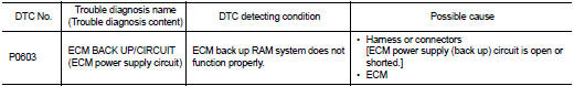
DTC CONFIRMATION PROCEDURE
1.PRECONDITIONING
If DTC Confirmation Procedure has been previously conducted, always perform the following procedure before conducting the next test.
1. Turn ignition switch OFF and wait at least 10 seconds.
2. Turn ignition switch ON.
3. Turn ignition switch OFF and wait at least 10 seconds.
>> GO TO 2.
2.PERFORM DTC CONFIRMATION PROCEDURE
1. Turn ignition switch ON wait at least 10 seconds.
2. Turn ignition switch OFF and wait at least 5 minutes.
3. Turn ignition switch ON, wait at least 10 seconds.
4. Repeat step 2 and 3 for five times.
5. Check 1st trip DTC.
Is 1st trip DTC detected? YES >> Proceed to EC-300, "Diagnosis Procedure".
NO >> INSPECTION END
Diagnosis Procedure
1.CHECK ECM POWER SUPPLY
1. Turn ignition switch OFF.
2. Disconnect ECM harness connector.
3. Check the voltage between ECM harness connector terminals.
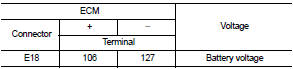
Is the inspection result normal? YES >> GO TO 2.
NO >> Perform the trouble diagnosis for power supply circuit.
2.CHECK INTERMITTENT INCIDENT
Perform GI-42, "Intermittent Incident".
Is the inspection result normal? YES >> GO TO 3.
NO >> Repair or replace error-detected parts.
3.PERFORM DTC CONFIRMATION PROCEDURE
1. Turn ignition switch ON.
2. Erase DTC.
3. Perform DTC confirmation procedure.
Refer to EC-300, "DTC Logic".
Is the 1st trip DTC P0603 displayed again? YES >> Replace ECM. Refer to EC-447, "Removal and Installation".
NO >> INSPECTION END
 P0524 engine oil pressure
DTC Logic
DTC DETECTION LOGIC
NOTE:
If DTC P0524 is displayed with DTC P0520, P0075, or P0081, perform trouble
diagnosis for DTC P0520,
P0075, or P0081 first. Refer to EC-176, "DTC Logic&qu ...
 P0605 ECM
DTC Logic
DTC DETECTION LOGIC
DTC CONFIRMATION PROCEDURE
1.PRECONDITIONING
If DTC Confirmation Procedure has been previously conducted, always perform
the following procedure
before conductin ...
Other materials:
Thermostat
Exploded View
1. Radiator hose (upper)
2. Water inlet
3. Rubber ring
4. Thermostat
A. To radiator
: Always replace after every
disassembly.
: N·m (kg-m, ft-lb)
Removal and Installation
REMOVAL
1. Drain engine coolant from radiator. Refer to CO-37, "Draining".
CAUTION:
...
Hood lock
Exploded View
1. Hood lock control cable assembly
2. Hood lock assembly
: Clip
: N·m (kg-m, ft-lb)
: Body grease
Hood lock
HOOD LOCK : Removal and Installation
REMOVAL
1. Remove front center grille. Refer to EXT-18, "Removal and Installation".
2. Remove crash zone sensor. Ref ...
Front power window switch (passenger side)
Component Function Check
1. CHECK FRONT POWER WINDOW SWITCH (PASSENGER SIDE) FUNCTION
Check front power window motor (passenger side) operation with front power
window switch (passenger side).
Is the inspection result normal?
YES >> INSPECTION END
NO >> Refer to PWC-22, "Di ...
