Nissan Juke Service and Repair Manual : Rear power window switch
Component Function Check
1. CHECK REAR POWER WINDOW SWITCH FUNCTION
Check rear power window motor operation with rear power window switch.
Is the inspection result normal? YES >> INSPECTION END
NO >> Refer to PWC-24, "Diagnosis Procedure".
Diagnosis Procedure
1.CHECK REAR POWER WINDOW SWITCH INPUT SIGNAL
1. Turn ignition switch OFF.
2. Disconnect rear power window switch connector.
3. Turn ignition switch ON.
4. Check voltage between rear power window switch harness connector and ground.
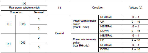
Is the inspection result normal? YES >> GO TO 3.
NO >> GO TO 2.
2.CHECK REAR POWER WINDOW SWITCH CIRCUIT
1. Turn ignition switch OFF.
2. Disconnect power window main switch connector.
3. Check continuity between rear power window switch harness connector and power window main switch harness connector.
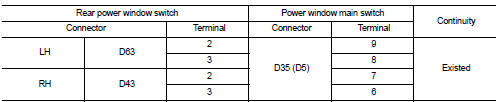
(): RHD models
4. Check continuity between rear power window switch harness connector and ground.
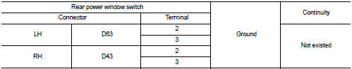
Is the inspection result normal? YES >> Replace power window main switch.
NO >> Repair or replace harness.
3.CHECK REAR POWER WINDOW SWITCH
Check rear power window switch.
Refer to PWC-25, "Component Inspection".
Is the inspection result normal? YES >> GO TO 4.
NO >> Replace rear power window switch.
4.CHECK INTERMITTENT INCIDENT
Refer to GI-42, "Intermittent Incident".
>> INSPECTION END
Component Inspection
1.CHECK REAR POWER WINDOW SWITCH
1. Turn ignition switch OFF.
2. Disconnect rear power window switch connector.
3. Check rear power window switch terminals under the following conditions.
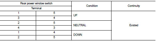
Is the inspection result normal? YES >> INSPECTION END
NO >> Replace rear power window switch.
 Front power window switch (passenger side)
Component Function Check
1. CHECK FRONT POWER WINDOW SWITCH (PASSENGER SIDE) FUNCTION
Check front power window motor (passenger side) operation with front power
window switch (passenger side).
...
 Power window motor
DRIVER SIDE
DRIVER SIDE : Component Function Check
1. CHECK FRONT POWER WINDOW MOTOR (DRIVER SIDE) OPERATION
Check front power window motor (driver side) operation with power window main
switch.
...
Other materials:
B1086 seat belt Pre-tensioner LH
DTC Logic
DTC DETECTION LOGIC
DTC CONFIRMATION PROCEDURE
1.CHECK SELF-DIAG RESULT
With CONSULT-III
1. Turn ignition switch ON.
2. Perform “Self Diagnostic Result” mode of “AIR BAG” using CONSULT-III.
Without CONSULT-III
1. Turn ignition switch ON.
2. Check the air bag warning la ...
4WD warning lamp does not turn on
Description
4WD warning lamp does not turn ON when the ignition switch is turned to ON.
Diagnosis Procedure
1.CHECK 4WD WARNING LAMP
Perform the trouble diagnosis for 4WD warning lamp. Refer to DLN-80,
"Diagnosis Procedure".
Is the inspection result normal?
YES >> Check eac ...
Brake and clutch (if so equipped) fluid
For additional brake and clutch fluid information, see “Capacities and recommended
fuel/lubricants” of this manual.
WARNING
• Use only new fluid from a sealed container. Old, inferior or contaminated
fluid may damage the brake and clutch systems. The use of improper fluids can dama ...
