Nissan Juke Service and Repair Manual : Power window motor
DRIVER SIDE
DRIVER SIDE : Component Function Check
1. CHECK FRONT POWER WINDOW MOTOR (DRIVER SIDE) OPERATION
Check front power window motor (driver side) operation with power window main switch.
Is the inspection result normal? YES >> INSPECTION END
NO >> Refer to PWC-26, "DRIVER SIDE : Diagnosis Procedure".
DRIVER SIDE : Diagnosis Procedure
1.CHECK FRONT POWER WINDOW MOTOR (DRIVER SIDE) INPUT SIGNAL
1. Turn ignition switch OFF.
2. Disconnect front power window motor (driver side) connector.
3. Turn ignition switch ON.
4. Check voltage between front power window motor (driver side) harness connector and ground.
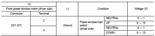
(): RHD models Is the inspection result normal? YES >> Replace front power window motor (driver side).
NO >> GO TO 2.
2.CHECK FRONT POWER WINDOW MOTOR (DRIVER SIDE) CIRCUIT
1. Turn ignition switch OFF.
2. Disconnect power window main switch connector.
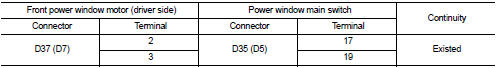
3. Check continuity between front power window motor (driver side) harness connector and power window main switch harness connector.
4. Check continuity between front power window motor (driver side) harness connector and ground.
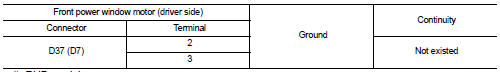
(): RHD models
Is the inspection result normal? YES >> Replace power window main switch.
NO >> Repair or replace harness.
Passenger side
PASSENGER SIDE : Component Function Check
1. CHECK FRONT POWER WINDOW MOTOR (PASSENGER SIDE) OPERATION
Check front power window motor (passenger side) operation with power window main switch or front power window switch (passenger side).
Is the inspection result normal? YES >> INSPECTION END
NO >> Refer to PWC-27, "PASSENGER SIDE : Diagnosis Procedure".
PASSENGER SIDE : Diagnosis Procedure
1.CHECK FRONT POWER WINDOW MOTOR (PASSENGER SIDE) INPUT SIGNAL
1. Turn ignition switch OFF.
2. Disconnect front power window motor (passenger side) connector.
3. Turn ignition switch ON.
4. Check voltage between front power window motor (passenger side) harness connector and ground.
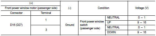
(): RHD models
Is the inspection result normal? YES >> Replace front power window motor (passenger side).
NO >> GO TO 2.
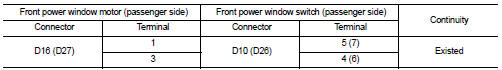
2.CHECK FRONT POWER WINDOW MOTOR (PASSENGER SIDE) CIRCUIT
1. Turn ignition switch OFF.
2. Disconnect front power window switch (passenger side) connector.
3. Check continuity between front power window motor (passenger side) harness connector and front power window switch (passenger side) harness connector.
4. Check continuity between front power window motor (passenger side) harness connector and ground.
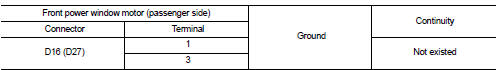
(): RHD models
Is the inspection result normal? YES >> Replace front power window switch (passenger side).
NO >> Repair or replace harness.
Rear LH
REAR LH : Component Function Check
1.CHECK REAR POWER WINDOW MOTOR LH OPERATION
Check rear power window motor LH operation with power window main switch or rear power window switch LH.
Is the inspection result normal? YES >> INSPECTION END
NO >> Refer to PWC-28, "REAR LH : Diagnosis Procedure".
REAR LH : Diagnosis Procedure
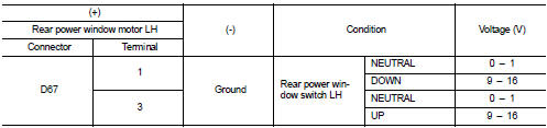
1.CHECK REAR POWER WINDOW MOTOR LH INPUT SIGNAL
1. Turn ignition switch OFF.
2. Disconnect rear power window motor LH connector.
3. Turn ignition switch ON.
4. Check voltage between rear power window motor LH harness connector and ground.
Is the inspection result normal? YES >> Replace rear power window motor LH.
NO >> GO TO 2.
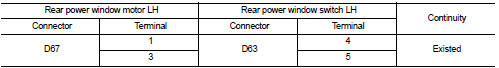
2.CHECK REAR POWER WINDOW MOTOR LH CIRCUIT
1. Turn ignition switch OFF.
2. Disconnect rear power window switch LH connector.
3. Check continuity between rear power window motor LH harness connector and rear power window switch LH harness connector.
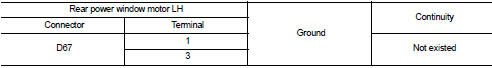
4. Check continuity between rear power window motor LH connector and ground.
Is the inspection result normal? YES >> Replace rear power window switch LH.
NO >> Repair or replace harness.
Rear RH
REAR RH : Component Function Check
1. CHECK REAR POWER WINDOW MOTOR RH OPERATION
Check rear power window motor RH operation with power window main switch or rear power window switch RH.
Is the inspection result normal? YES >> INSPECTION END
NO >> Refer to PWC-29, "REAR RH : Diagnosis Procedure".
REAR RH : Diagnosis Procedure
1.CHECK REAR POWER WINDOW MOTOR RH INPUT SIGNAL
1. Turn ignition switch OFF.
2. Disconnect rear power window motor RH connector.
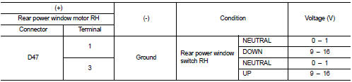
3. Turn ignition switch ON.
4. Check voltage between rear power window motor RH harness connector and ground.
Is the inspection result normal? YES >> Replace rear power window motor RH.
NO >> GO TO 2.
2.CHECK REAR POWER WINDOW MOTOR RH CIRCUIT
1. Turn ignition switch OFF.
2. Disconnect rear power window switch RH connector.
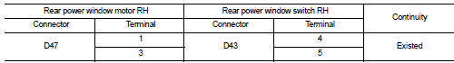
3. Check continuity between rear power window motor RH harness connector and rear power window switch RH harness connector.
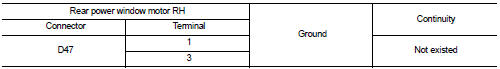
4. Check continuity between rear power window motor RH harness connector and ground.
Is the inspection result normal? YES >> Replace rear power window switch RH.
NO >> Repair or replace harness.
 Rear power window switch
Component Function Check
1. CHECK REAR POWER WINDOW SWITCH FUNCTION
Check rear power window motor operation with rear power window switch.
Is the inspection result normal?
YES >> INSPECTIO ...
 Encoder circuit
Component Function Check
1.CHECK ENCODER OPERATION
Check that front driver side door glass perform AUTO UP/DOWN operation
normally when power window
main switch is operated.
Is the inspection ...
Other materials:
B2614 ACC relay circuit
DTC Logic
DTC DETECTION LOGIC
DTC CONFIRMATION PROCEDURE
1.PERFORM DTC CONFIRMATION PROCEDURE
1. Turn the power supply position to ACC under the following conditions, and
wait for 2 second or more.
CVT models
- Selector lever is in the P or N position
- Do not depress brake pedal
M/T m ...
Intelligent Key system (if so equipped)
WARNING
• Radio waves could adversely affect electric medical equipment. Those who
use a pacemaker should contact the electric medical equipment manufacturer for the
possible influences before use.
• The Intelligent Key transmits radio waves when the buttons are pushed. The FAA
advises t ...
Additional service when replacing transaxle assembly
Description
Perform the following work after the transaxle assembly is replaced.
Erasing the calibration data
• The TCM acquires calibration data (individual characteristic value) of each
solenoid that is stored in the
ROM assembly (in the control valve). This enables the TCM to perform ac ...
