Nissan Juke Service and Repair Manual : Encoder circuit
Component Function Check
1.CHECK ENCODER OPERATION
Check that front driver side door glass perform AUTO UP/DOWN operation normally when power window main switch is operated.
Is the inspection result normal? YES >> INSPECTION END
NO >> Refer to PWC-30, "Diagnosis Procedure".
Diagnosis Procedure
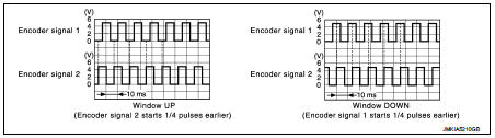
1.CHECK ENCODER PULSE SIGNAL
1. Turn ignition switch ON.
2. Check signal between power window main switch harness connector and ground with oscilloscope.
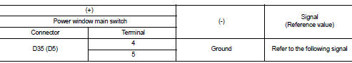
(): RHD models
Is the inspection result normal? YES >> Replace power window main switch.
NO >> GO TO 2.
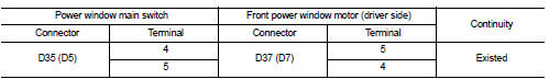
2.CHECK ENCODER SIGNAL CIRCUIT
1. Turn ignition switch OFF.
2. Disconnect power window main switch connector and front power window motor (driver side) connector.
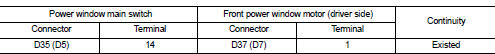
3. Check continuity between power window main switch harness connector and front power window motor (driver side) harness connector.
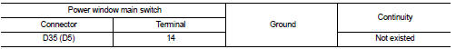
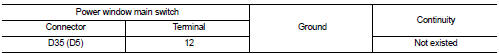
4. Check continuity between power window main switch harness connector and ground.
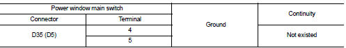
(): RHD models Is the inspection result normal? YES >> GO TO 3.
NO >> Repair or replace harness.
3.CHECK ENCODER POWER SUPPLY
1. Connect power window main switch connector.
2. Turn ignition switch ON.
3. Check voltage between front power window motor (driver side) harness connector and ground.
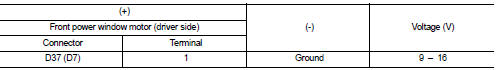
(): RHD models Is the inspection result normal? YES >> GO TO 5.
NO >> GO TO 4.
4.CHECK ENCODER POWER SUPPLY CIRCUIT
1. Turn ignition switch OFF.
2. Disconnect power window main switch connector.
3. Check continuity between power window main switch harness connector and front power window motor (driver side) harness connector.
4. Check continuity between power window main switch harness connector and ground.
(): RHD models Is the inspection result normal? YES >> Replace power window main switch.
NO >> Repair or replace harness.
5.CHECK ENCODER GROUND CIRCUIT 1
1. Turn ignition switch OFF.
2. Disconnect power window main switch connector.
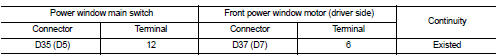
3. Check continuity between power window main switch harness connector and front power window motor (driver side) harness connector.
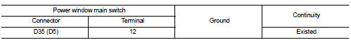
4. Check continuity between power window main switch harness connector and ground.
(): RHD models
Is the inspection result normal? YES >> GO TO 6.
NO >> Repair or replace harness.
6.CHECK ENCODER GROUND CIRCUIT 2
1. Connect power window main switch connector.
2. Check continuity between power window main switch harness connector and ground.
(): RHD models
Is the inspection result normal? YES >> Replace front power window motor (driver side).
NO >> Replace power window main switch.
 Power window motor
DRIVER SIDE
DRIVER SIDE : Component Function Check
1. CHECK FRONT POWER WINDOW MOTOR (DRIVER SIDE) OPERATION
Check front power window motor (driver side) operation with power window main
switch.
...

Other materials:
Refrigerant
Description
CONNECTION OF SERVICE TOOLS AND EQUIPMENT
1. Shut-off valve
2. A/C service valve
3. Recovery/recycling/recharging
equipment
4. Vacuum pump
5. Manifold gauge set
6. Refrigerant container (HFC-134a)
7. Weight scale
A. Preferred (best) method
B. Alternative method
C. For ...
Manual Transmission (MT)
WARNING
• Do not downshift abruptly on slippery roads. This may cause a loss
of control.
• Do not over-rev the engine when shifting to a lower gear. This may cause a loss
of control or engine damage.
• When the high fluid temperature protection mode or fail-safe operation occurs, ...
Clutch master cylinder
LHD : Exploded View
1. Reservoir hose
2. Reservoir tank
3. Master cylinder
LHD : Removal and Installation
REMOVAL
CAUTION:
• Keep painted surface on the body or other parts free of clutch fluid. If it
spills, wipe up immediately
and wash the affected area with water.
• Never disas ...
