Nissan Juke Service and Repair Manual : Front fog lamp aiming adjustment
Description
PREPARATION BEFORE ADJUSTING
NOTE
:
For details, refer to the regulations in your own country.
Before performing aiming adjustment, check the following.
ŌĆó Adjust the tire pressure to the specification.
ŌĆó Fill with fuel, engine coolant and each oil.
ŌĆó Maintain the unloaded vehicle condition. (Remove luggage from the passenger compartment and the luggage room.) NOTE
:
Do not remove the temporary tire, jack and on-vehicle tool.
ŌĆó Wipe out dirt on the headlamp.
CAUTION:
Never use organic solvent (thinner, gasoline etc.)
ŌĆó Ride alone on the driver seat.
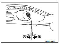
AIMING ADJUSTMENT SCREW
ŌĆó Turn the aiming adjusting screw for adjustment.
A: DOWN
B: UP
ŌĆó For the position and direction of the adjusting screw, refer to the figure.
NOTE
:
A screwdriver or hexagonal wrench [6 mm (0.24 in)] can be used
for adjustment.
Aiming Adjustment Procedure
1. Place the screen.
NOTE
:
ŌĆó Stop the vehicle facing the wall.
ŌĆó Place the board on a plain road vertically.
2. Face the vehicle with the screen. Maintain 10 m (32.8 ft) between the front
fog lamp center and the
screen.
3. Start the engine. Illuminate the front fog lamp.
CAUTION:
Never cover the lens surface with a tape etc. The lens is made of resin.
NOTE:
Shut off the headlamp light with the board to prevent from illuminating the adjustment screen.
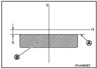
4. Adjust the cutoff line height (A) with the aiming adjustment screw so that the distance (X) between the horizontal center line of front fog lamp (H) and (A) becomes 200 mm (7.87 in).
Front fog lamp light distribution on the screen
A : Cutoff line
B : High illuminance area
H : Horizontal center line of front fog lamp
V : Vertical center line of front fog lamp
X : Cutoff line height
 Headlamp aiming adjustment
LHD
LHD : Description
PREPARATION BEFORE ADJUSTING
NOTE:
ŌĆó For details, refer to the regulations in your own country.
ŌĆó Perform aiming if the vehicle front body has been repaired and/or the h ...

Other materials:
P0706 transmission range sensor A
DTC Logic
DTC DETECTION LOGIC
DTC CONFIRMATION PROCEDURE
1.PREPARATION BEFORE WORK
If another "DTC CONFIRMATION PROCEDURE" occurs just before, turn ignition
switch OFF and wait for at
least 10 seconds, then perform the next test.
>> GO TO 2.
2.PERFORM DTC CONFIRMATION ...
Exhaust gas (carbon monoxide)
WARNING
ŌĆó Do not breathe exhaust gases; they contain colorless and odorless carbon
monoxide. Carbon monoxide is dangerous. It can cause unconsciousness or death.
ŌĆó If you suspect that exhaust fumes are entering the vehicle, drive with all windows
fully open, and have the vehicle inspected ...
P0087 fuel pump
DTC Logic
DTC DETECTION LOGIC
NOTE:
ŌĆó Conditions for applying the diagnostic procedure to the stored DTCs:
The DTC becomes present during the first 30 seconds after the engine starts.
ŌĆó In low ambient temperature conditions, diagnostic cannot make difference
between a normal long engine ...
