
Nissan Juke Service and Repair Manual : P0643 sensor power supply
DTC Logic
DTC DETECTION LOGIC
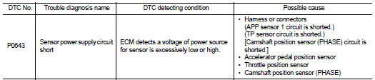
DTC CONFIRMATION PROCEDURE
1.PRECONDITIONING
If DTC Confirmation Procedure has been previously conducted, always turn ignition switch OFF and wait at least 10 seconds before conducting the next test.
TESTING CONDITION:
Before performing the following procedure, confirm that battery voltage is more
than 10 V at idle.
>> GO TO 2.
2.PERFORM DTC CONFIRMATION PROCEDURE
1. Start engine and let it idle for 1 second.
2. Check DTC.
Is DTC detected? YES >> Go to EC-686, "Diagnosis Procedure".
NO >> INSPECTION END
Diagnosis Procedure
1.CHECK GROUND CONNECTION
1. Turn ignition switch OFF.
2. Check ground connection E21 and E38. Refer to Ground Inspection in GI-44, "Circuit Inspection".
Is the inspection result normal? YES >> GO TO 2.
NO >> Repair or replace ground connection.
2.CHECK ACCELERATOR PEDAL POSITION SENSOR 1 POWER SUPPLY CIRCUIT
1. Disconnect accelerator pedal position (APP) sensor harness connector.
2. Turn ignition switch ON.
3. Check the voltage between APP sensor harness connector and ground.
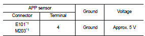
*1: LHD models or RHD models with CVT *2: RHD models with M/T
Is the inspection result normal? YES >> GO TO 7.
NO >> GO TO 3.
3.CHECK SENSOR POWER SUPPLY CIRCUIT
Check harness for short to power and short to ground, between the following terminals.
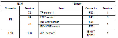
*1: LHD models or RHD models with CVT *2: RHD models with M/T
Is the inspection result normal? YES >> GO TO 4.
NO >> Repair short to ground or short to power in harness or connectors.
4.CHECK CAMSHAFT POSITION SENSOR (PHASE)
Refer to EC-662, "Component Inspection".
Is the inspection result normal? YES >> GO TO 5.
NO >> Replace camshaft position sensor (PHASE).
5.CHECK THROTTLE POSITION SENSOR
Refer to EC-646, "Component Inspection".
Is the inspection result normal? YES >> GO TO 9.
NO >> GO TO 6.
6.REPLACE ELECTRIC THROTTLE CONTROL ACTUATOR
Replace electric throttle control actuator. Refer to EM-163, "Exploded View".
>> INSPECTION END
7.CHECK APP SENSOR
Refer to EC-749, "Component Inspection".
Is the inspection result normal? YES >> GO TO 9.
NO >> GO TO 8.
8.REPLACE ACCELERATOR PEDAL ASSEMBLY
Replace accelerator pedal assembly. Refer to ACC-3, "Exploded View".
>> INSPECTION END
9.CHECK INTERMITTENT INCIDENT
Refer to GI-42, "Intermittent Incident".
>> INSPECTION END
 P0607 ECM
DTC Logic
DTC DETECTION LOGIC
DTC CONFIRMATION PROCEDURE
1.PERFORM DTC CONFIRMATION PROCEDURE
1. Turn ignition switch ON.
2. Check DTC.
Is DTC detected?
YES >> Proceed to EC-685, &quo ...
 P0850 PNP switch
Description
When the selector lever position is P or N (CVT), Neutral position (M/T),
park/neutral position (PNP) signal is
ON.
DTC Logic
DTC DETECTION LOGIC
DTC CONFIRMATION PROCEDURE
1.INS ...
Other materials:
Drive belt
Exploded View
1. Alternator
2. Drive belt auto-tensioner
3. Crankshaft pulley
4. A/C compressor
5. Water pump
6. Drive belt
A. Possible use range
B.
Range when new drive belt is installed
C. Indicator
Checking
WARNING:
Perform this step when engine is stopped.
• Check that ...
Shift position indicator circuit
Component Parts Function Inspection
1.CHECK SHIFT POSITION INDICATOR
1. Start the engine.
2. Shift selector lever.
3. Check that the selector lever position and the shift position indicator on
the combination meter are identical.
Is the inspection result normal?
YES >> INSPECTION END ...
Precaution for Harness Repair
• Solder the repair part, and wrap it with tape. [Twisted wire fray
must be 110 mm (4.33 in) or less.]
• Never bypass the repair point with wire. (If it is bypassed, the turnout
point cannot be separated and the twisted wire characteristics
are lost.)
...
