Nissan Juke Service and Repair Manual : U1000 can comm circuit
Description
CAN (Controller Area Network) is a serial communication system for real time application. It is an on-vehicle multiplex communication system with high data communication speed and excellent error detection ability.
Many electronic control units are equipped onto vehicles, and each control unit shares information and links with other control units during operation (not independent). In CAN communication, control units are connected with two communication lines (CAN-H line, CAN-L line) allowing a high rate of information transmission with less wiring. Each control unit transmits/receives data but selectively reads required data only.
CAN Communication Signal Chart. Refer to LAN-31, "CAN COMMUNICATION SYSTEM : CAN Communication Signal Chart".
DTC Logic
DTC DETECTION LOGIC
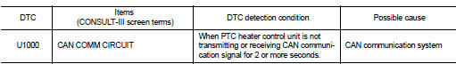
DTC CONFIRMATION PROCEDURE
1.PERFORM SELF-DIAGNOSIS
 With CONSULT-III
1. Turn ignition switch ON and wait for 2 seconds or more.
2. Select тАЬSelf Diagnostic ResultтАЭ mode of тАЬPTC HEATERтАЭ using CONSULT-.III 3. Check DTC.
Is DTC detected? YES >> Refer to HAC-275, "Diagnosis Procedure".
NO >> Check intermittent incident. Refer to GI-42, "Intermittent Incident".
Diagnosis Procedure
1.CHECK CAN COMMUNICATION SYSTEM
Check CAN communication system. Refer to LAN-17, "Trouble Diagnosis Flow Chart".
>> INSPECTION END

 U1010 control unit (can)
Description
Initial diagnosis of A/C auto amp.
DTC Logic
DTC DETECTION LOGIC
DTC CONFIRMATION PROCEDURE
1.PERFORM SELF-DIAGNOSIS
With CONSULT-III
1. Turn ignition switch ON.
2. Select тАЬSel ...
Other materials:
How to enable/disable the Steering Assist
Steering-wheel mounted control (right): Used for ProPILOT Assist settings and menu navigation.
Vehicle information display: The digital hub for viewing driver assistance settings.
Steering Assist switch: The physical toggle located on the instrument ...
Squeak and rattle trouble diagnoses
Work Flow
CUSTOMER INTERVIEW
Interview the customer if possible, to determine the conditions that exist
when the noise occurs. Use the Diagnostic
Worksheet during the interview to document the facts and conditions when the
noise occurs and any of
the customer's comments; refer to MIR-39, & ...
Three-way catalyst
The three-way catalyst is an emission control device installed in the exhaust
system. Exhaust gases in the three-way catalyst are burned at high temperatures
to help reduce pollutants.
WARNING
тАв The exhaust gas and the exhaust system are very hot. Keep people, animals
or flammable material ...
