Nissan Juke Service and Repair Manual : Periodic maintenance
ROAD WHEEL
Adjustment
BALANCING WHEELS (ALUMINUM WHEEL)
Preparation Before Adjustment Using releasing agent, remove double-faced adhesive tape from the road wheel.
CAUTION:
• Be careful not to scratch the road wheel during removal.
• After removing double-faced adhesive tape, wipe clean traces of releasing agent from the road wheel.
Wheel Balance Adjustment • The details of the adjustment procedure are different for each model of wheel balancer. Therefore, refer to each instruction manual.
• If a tire balance machine has adhesion balance weight mode settings and drive-in weight mode setting, select and adjust a drive-in weight mode suitable for aluminum wheels.
1. Set road wheel on tire balance machine using the center hole as a guide. Start the tire balance machine.
2. When inner and outer unbalance values are shown on the tire balance machine indicator, multiply outer unbalance value by 5/3 to determine balance weight that should be used. Select the outer balance weight with a value closest to the calculated value above and install to the designated outer position of, or at the designated angle in relation to the road wheel.
CAUTION:
• Never install the inner balance weight before installing the outer balance
weight.
• Before installing the balance weight, always to clean the mating surface of the road wheel.
a. Indicated unbalance value × 5/3 = balance weight to be installed
Calculation example:
23 g (0.81 oz) × 5/3 = 38.33 g (1.35 oz) ⇒ 40 g (1.41 oz) balance
weight (closer to calculated balance weight value)
NOTE
:
Note that balance weight value must be closer to the calculated
balance weight value.
Example:
37.4 ⇒ 35 g (1.23 oz)
37.5 ⇒ 40 g (1.41 oz)
b. Installed balance weight in the position.
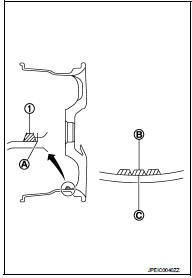
• When installing balance weight (1) to road wheels, set it into the grooved area (A) on the inner wall of the road wheel as shown in the figure so that the balance weight center (B) is aligned with the tire balance machine indication position (angle) (C).
CAUTION:
• Always use genuine NISSAN balance weights.
• Balance weights are non-reusable; always replace with new ones.
• Never install three or more sheets of balance weigh
t.
c. If calculated balance weight value exceeds 50 g (1.76 oz), install two balance weight sheets in line with each other as shown in the figure.
CAUTION:
Never install one balance weight sheet on top of another.
3. Start the tire balance machine again.
4. Install drive-in balance weight on inner side of road wheel in the tire balance machine indication position (angle).
CAUTION:
Never install three or more balance weight.
5. Start the tire balance machine. Check that the inner and outer residual unbalance value is within the allowable unbalance value.
CAUTION:
If either residual unbalance value exceeds limit, repeat installation
procedures.
Allowable unbalance value Dynamic (At flange) : Refer to WT-9, "Road Wheel".
Static (At flange) : Refer to WT-9, "Road Wheel".
BALANCING WHEELS (STEEL WHEEL)
Preparation Before Adjustment Remove balance weight from the road wheel.
Wheel Balance Adjustment • The details of the adjustment procedure are different for each model of wheel balancer. Therefore, refer to each instruction manual.
• If a tire balance machine has adhesion balance weight mode settings and drive-in weight mode setting, select and adjust a drive-in weight mode suitable for steel wheels.
1. Set road wheel to wheel balancer, and then start wheel balancer.
2. Install balance weight to road wheel according to the unbalance and position (angle) displayed on wheel balancer.
CAUTION:
• Always use genuine NISSAN balance weights.
• Balance weights are non-reusable; always replace with new ones.
• Always use a plastic hammer when attaching the weight.
• Never install three or more balance weights on one side.
3. Start the tire balance machine. Check that the inner and outer residual unbalance value is within the allowable unbalance value.
CAUTION:
If either residual unbalance value exceeds limit, repeat installation
procedures.
Allowable unbalance value Dynamic (At flange) : Refer to WT-9, "Road Wheel".
Static (At flange) : Refer to WT-9, "Road Wheel".
Tire Rotation
• Follow the maintenance schedule for tire rotation service intervals.
Refer to MA-5, "General Maintenance".
• When installing the wheel, tighten wheel nuts to the specified torque. Refer to WT-7, "Exploded View".
CAUTION:
• Never include the T-type spare tire when rotating the tires.
• When installing wheels, tighten them diagonally by dividing the work two to three times in order to prevent the wheels from developing any distortion.
• Be careful not to tighten wheel nut at torque exceeding the criteria.
• Use NISSAN genuine wheel nut.
 Symptom diagnosis
NOISE, VIBRATION AND HARSHNESS (NVH) TROUBLESHOOTING
NVH Troubleshooting Chart
Use the chart below to find the cause of the symptom. If necessary, repair or
replace these parts.
×: Applic ...
 Removal and installation
Road wheel tire assembly
Exploded View
1. Tire assembly
: N·m (kg-m, ft-lb)
Removal and Installation
REMOVAL
1. Remove wheel nuts.
2. Remove tire assembly.
INSTALLATION
Install in the re ...
Other materials:
Precautions on seat belt usage
If you are wearing your seat belt properly adjusted, and you are sitting upright
and well back in your seat with both feet on the floor, your chances of being injured
or killed in an accident and/or the severity of injury may be greatly reduced. NISSAN
strongly encourages you and all of your p ...
Lights
Headlight assembly
Map light
Room light
High-mounted stop light
Rear combination light
Door mirror turn signal light (if so equipped)
Cargo light
License plate light
Fog light (if so equipped)
...
Vehicle loading information
WARNING
It is extremely dangerous to ride in the cargo area inside the vehicle.
In the event of a collision, individuals positioned in these unsecured areas are significantly more likely to suffer serious injury or fatalities.
Never allow passengers to ...
