Nissan Juke Service and Repair Manual : Door sash tape
Exploded View

1. Front door panel
2. Front door sash tape
3. Rear door sash tape
4. Rear door panel
 : Do not reuse
Front door sash tape
FRONT DOOR SASH TAPE : Removal and Installation
REMOVAL
Heat door sash tape surface using a dryer, and then peel door sash tape.
CAUTION:
Never damage painted surface of door panel.
INSTALLATION
NOTE
:
For installation position of door sash tape, refer to the position as shown in
the figure.
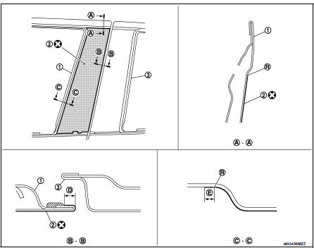
1. Front door panel
2. Front door sash tape
3. Rear door panel
R. Radius
 : Do not reuse
D : 2.0 mm (0.08 in)
E : 4.0 mm (0.16 in)
CAUTION:
• Degrease door panel mounting surface for sash tape.
• Paint grain or dust on mounting surface of sash tape may spoil exterior appearance if it remains.Clean the mounting surface and check that no paint grain or dust remains, before starting the operation.
• Never reuse blackout tape.
1. Affix door sash tape align blackout tape upper portion to rear door outer upper end.
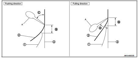
2. Affix door sash tape (2) to door panel (3) by applying pressure using a squeegee (A) while peeling offrelease coated paper (1).
NOTE
:
• Peel release coated paper at distance of 10 – 20 mm (0.394 – 0.787 in) ahead
(B) of squeegee and
affixblackout paper.
• To prevent any bubbles from forming, slightly lift the portion, not yet affixed using squeegee, so that portion dose not contact with panel surface. Apply pressure and affix at a low and constant speed usingsqueegee tilted at 40 – 50° angle (pushing direction) (C) 30 – 45° angle (pulling direction) (D).
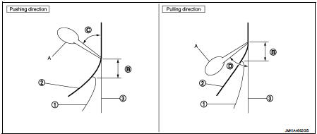
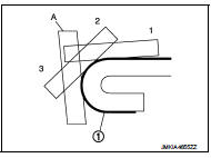
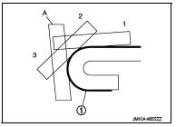
3. For small radius portion of hemming part, gradually apply pressure and affix door sash tape (1) using squeegee (A) in 1 – 3 steps.
CAUTION:
Never wash the vehicle with in 24 hours so as to keep adhesive.
Rear door sash tape
REAR DOOR SASH TAPE : Removal and Installation
REMOVAL
Heat door sash tape surface using a dryer, and then peel door sash tape.
CAUTION:
Never damage painted surface of door pane
l.
INSTALLATION
NOTE
:
For installation position of door sash tape, refer to the position as shown in
the figure.
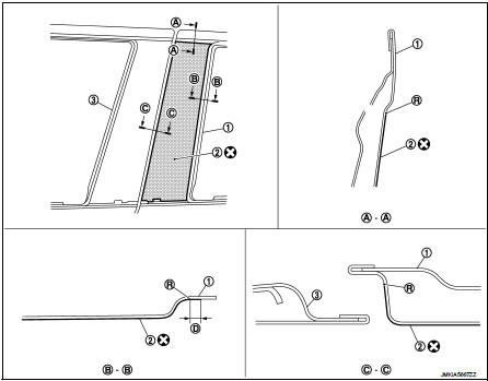
1. Rear door panel
2. Rear door sash tape
3. Front door panel
R. Radius
 : Do not reuse
D : 2.0 mm (0.08 in)
CAUTION:
• Degrease door panel mounting surface for door sash tape.
• Paint grain or dust on mounting surface of door sash tape may spoil exterior appearance if it remains. Clean the mounting surface and check that no paint grain or dust remains, before starting the operation.
• Never reuse door sash tape.
1. Affix door sash tape align door sash tape upper portion to rear door outer upper end.
2. Affix door sash tape (2) to door panel (3) by applying pressure using a squeegee (A) while peeling off release coated paper (1).
NOTE
:
• Peel release coated paper at distance of 10 – 20 mm (0.394 – 0.787 in) ahead
(B) of squeegee and
affixblackout paper.
• To prevent any bubbles from forming, slightly lift the portion, not yet affixed using squeegee, so that portion dose not contact with panel surface. Apply pressure and affix at a low and constant speed using squeegee tilted at 40 – 50° angle (pushing direction) (C) 30 – 45° angle (pulling direction) (D).
3. For small radius portion of hemming part, gradually apply pressure and affix door sash tape (1) using squeegee (A) in 1 – 3 steps.
CAUTION:
Never wash the vehicle with in 24 hours so as to keep adhesive.
 Door outside molding
Exploded View
1. Front door panel
2. Front door outside molding
3. Rear door panel
4. Rear door outside molding
5. Door glass
: Pawl
Front door outside molding
FRONT DOOR OUTSIDE MOLDING ...
 Rear fender cover
Exploded View
1. Rear fender cover
2. Rear fender
Removal and Installation
REMOVAL
Disengage rear fender cover fixing clips using remover tool (A), and
then remove rear fender cover.
CAUTI ...
Other materials:
B2098 ignition relay on stuck
Description
The ignition relay integrated in IPDM E/R is operated with ignition switch ON
signal from the ignition switch.
DTC Logic
DTC DETECTION LOGIC
1.PERFORM DTC CONFIRMATION PROCEDURE
1. Turn ignition switch ON.
2. Check DTC in “Self Diagnostic Result” mode of “IPDM E/R” usin ...
Compressor
Exploded View
REMOVAL
1. High-pressure flexible hose
2. O-ring
3. Compressor
4. O-ring
5. Low-pressure flexible hose
A. To condenser
B. To evaporator
: N·m (kg-m, ft-lb)
DISASSEMBLY
1. Compressor unit
2. Field coil
3. Snap ring
4. Pulley assembly
5. Snap ring
6. Shim
7. ...
Air fresheners
Most air fresheners use a solvent that could affect the vehicle interior. If
you use an air freshener, take the following precautions:
• Hanging-type air fresheners can cause permanent discoloration when they contact
vehicle interior surfaces. Place the air freshener in a location that allows ...
