Nissan Juke Service and Repair Manual : Vacuum lines
MR16DDT : Removal and Installation
REMOVAL
1. Remove the vacuum hose and vacuum piping.
2. Perform inspection after removal. Refer to BR-115, "MR16DDT : Inspection".
INSTALLATION
Note the following, install the vacuum hose.
• When installing vacuum hose, insert it until its tip reaches the back-end of length (A) or further as shown in the figure.
CAUTION:
Never use lubricating oil during assembly.
A : 24 mm (0.95 in) or more
- Face the paint mark of vacuum hose (engine side) upward to assemble.
- Face the paint mark of vacuum hose (brake booster side) to the vehicle front side to assemble.
- For clamp mounting direction (the orientation of pawl), refer to BR- 115, "MR16DDT : Exploded View".
MR16DDT : Inspection
INSPECTION AFTER REMOVAL
Appearance
Check for correct assembly, damage and deterioration.
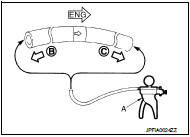
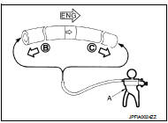
Check Valve Airtightness • Use a handy vacuum pump (A) to check.
When connected to the booster side (B): Vacuum should decrease within 1.3 kPa (9.8 mmHg, 0.38 inHg, 0.013 bar) for 15 seconds under a vacuum of −66.7 kPa (−500 mmHg, −19.70 inHg, −0.667 bar).
When connected to the engine side (C): Vacuum should not exist.
• Replace vacuum hose if vacuum hose is malfunctioning.
HR16DE : Exploded View
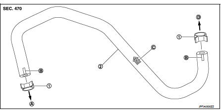
1. Clamp
2. Vacuum hose (built-in check valve)
A. To intake manifold
B. Paint mark
C. Stamp indicating engine direction
D. To brake booster
HR16DE : Removal and Installation
REMOVAL
1. Remove the vacuum hose and vacuum piping.
2. Perform inspection after removal. Refer to BR-117, "HR16DE : Inspection".
INSTALLATION
Note the following, install the vacuum hose.
• When installing vacuum hose, insert it until its tip reaches the back-end of length (A) or further as shown in the figure.
CAUTION:
Never use lubricating oil during assembly.
A : 24 mm (0.95 in) or more
- Face the paint marks upward to assemble.
- For clamp mounting direction (the orientation of pawl), refer to BR- 116, "HR16DE : Exploded View".
HR16DE : Inspection
INSPECTION AFTER REMOVAL
Appearance
Check for correct assembly, damage and deterioration.
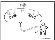
Check Valve Airtightness • Use a handy vacuum pump (A) to check.
When connected to the booster side (B): Vacuum should decrease within 1.3 kPa (9.8 mmHg, 0.38 inHg, 0.013 bar) for 15 seconds under a vacuum of −66.7 kPa (−500 mmHg, −19.70 inHg, −0.667 bar).
When connected to the engine side (C): Vacuum should not exist.
• Replace vacuum hose assembly if vacuum hose and check valve are malfunctioning.
K9K : Exploded View
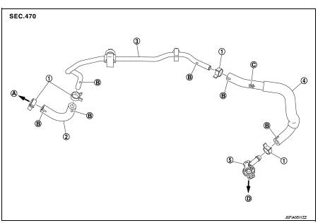
1. Clamp
2. Vacuum hose
3. Vacuum piping
4. Vacuum hose (built-in check valve)
5. Connector
A. To brake booster
B. Paint mark
C. Stamp indicating engine direction
D. To vacuum pump
K9K : Removal and Installation
REMOVAL
1. Remove air duct and air cleaner case. Refer to EM-280, "Removal and Installation".
2. Remove the vacuum hose and connector.
INSTALLATION
Note the following, install the vacuum hose.
• When installing vacuum hose, insert it until its tip reaches the back-end of length (A) or further as shown in the figure.
CAUTION:
Never use lubricating oil during assembly.
A : 24 mm (0.95 in) or more
- Face the paint mark of vacuum hose (built-in check valve, connector side) upward to assemble.
- Face the other paint marks to vehicle front side to assemble.
- For clamp mounting direction (the orientation of pawl), refer to BR- 117, "K9K : Exploded View".
K9K : Inspection
INSPECTION AFTER REMOVAL
Appearance
Check for correct assembly, damage and deterioration.
Check Valve Airtightness • Use a handy vacuum pump (A) to check.
When connected to the booster side (B): Vacuum should decrease within 1.3 kPa (9.8 mmHg, 0.38 inHg, 0.013 bar) for 15 seconds under a vacuum of −66.7 kPa (−500 mmHg, −19.70 inHg, −0.667 bar).
When connected to the engine side (C): Vacuum should not exist.
• Replace vacuum hose assembly if vacuum hose and check valve are malfunctioning.
 Brake booster
Exploded View
2WD
MR16DDT, HR16DE
1. Master cylinder assembly
2. Vacuum pipe
3. Brake booster
4. Lock nut
5. Clevis
6. Gasket
: N·m (kg-m, ft-lb)
K9K
1. Master cylinder assembly
...
 Front disc brake
Brake pad : Exploded View
MR16DDT
1. Cylinder body
2. Inner shim
3. Inner pad (with pad wear sensor)
4. Pad retainer
5. Torque member
6. Outer pad
7. Outer shim
1: Apply MOLYKOTE® AS88 ...
Other materials:
When traveling or registering your vehicle in another country
When planning to travel in another country, you should first find out if the
fuel available is suitable for your vehicle’s engine.
Using fuel with an octane rating that is too low may cause engine damage. All
gasoline vehicles must be operated with unleaded gasoline.
Therefore, avoid taking ...
System
Relay control system
RELAY CONTROL SYSTEM : System Diagram
*1: Except for MR16DDT engine models
*2: For MR16DDT engine models
RELAY CONTROL SYSTEM : System Description
IPDM E/R activates the internal control circuit to perform the relay ON-OFF
control according to the input signals
from va ...
Removal and Installation
REMOVAL
1. Remove engine assembly. Refer to EM-55, "2WD : Exploded View" (2WD) ,
EM-59, "4WD : Exploded
View" (4WD).
2. Remove oil pan (lower). Refer to EM-41, "Removal and Installation".
3. Remove front cover, and other related parts. Refer to EM-67, "Explod ...
