Nissan Juke Service and Repair Manual : Brake booster
Exploded View
2WD
MR16DDT, HR16DE
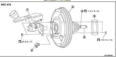
1. Master cylinder assembly
2. Vacuum pipe
3. Brake booster
4. Lock nut
5. Clevis
6. Gasket
 : N┬Ěm (kg-m, ft-lb)
K9K
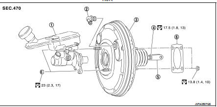
1. Master cylinder assembly
2. Vacuum pipe
3. Brake booster
4. Lock nut
5. Clevis
6. Gasket
 : N┬Ěm (kg-m, ft-lb)
4WD
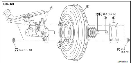
1. Master cylinder assembly
2. Brake booster
3. Lock nut
4. Clevis
5. Gasket
: N┬Ěm (kg-m, ft-lb)
Removal and installation
REMOVAL
1. Perform inspection before removal. Refer to BR-113, "Inspection and Adjustment".
2. Remove cowl top and cowl top extension. Refer to EXT-20, "Removal and Installation".
3. Remove brake master cylinder assembly. Refer to BR-108, "Removal and Installation".
4. Remove vacuum hose from brake booster.
ÔÇó MR16DDT: Refer to BR-115, "MR16DDT : Removal and Installation".
ÔÇó HR16DE: Refer to BR-116, "HR16DE : Removal and Installation".
ÔÇó K9K: Refer to BR-117, "K9K : Removal and Installation".
5. Remove low-pressure flexible hose.
ÔÇó HR16DE: Refer to HA-35, "LOW-PRESSURE FLEXIBLE HOSE : Removal and Installation".
ÔÇó MR16DDT: Refer to HA-91, "LOW-PRESSURE FLEXIBLE HOSE : Removal and Installation".
ÔÇó K9K: Refer to HA.
6. Remove snap pin (1) and clevis pin (2). Refer to BR-88, "Exploded View".
7. Remove nuts on brake booster and brake pedal assembly.
CAUTION:
Hold the brake booster so as to avoid dropping out
.
8. Remove brake booster.
CAUTION:
Never deform or bend the brake tubes.
NOTE:
If removing brake booster is difficult, remove clevis from brake booster.
9. Remove vacuum pipe from brake booster. (2WD) 10. Perform inspection after removal. Refer to BR-113, "Inspection and Adjustment".

INSTALLATION
CAUTION:
Never spill or splash brake fluid on painted surfaces. Brake fluid may seriously
damage paint. Wipe it
off immediately and wash with water if it gets on a painted surface.
Note the following, and install in the reverse order of removal.
ÔÇó Set vacuum pipe angle (A) as shown in the figure. [2WD (MR16DDT and HR16DE)]
A : 28 ÔÇô 38┬░
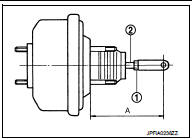
![ÔÇó Set vacuum pipe angle (A) as shown in the figure. [2WD (K9K)]](images/books/335/33/4.html13.gif)
ÔÇó Set vacuum pipe angle (A) as shown in the figure. [2WD (K9K)]
A : 28 ÔÇô 38┬░
ÔÇó Be careful not to damage brake booster stud bolt threads. If brake booster is tilted during installation, the dash panel may damage the threads.
ÔÇó Never deform or bend the brake tubes when installing the brake booster.
ÔÇó Always use a gasket between the brake booster and the dash panel.
ÔÇó Replace the clevis pin if it is damaged. Refer to BR-90, "Inspection and Adjustment".
ÔÇó Perform the air bleeding. Refer to BR-81, "Bleeding Brake System".
ÔÇó Check each item of brake pedal. Adjust it if the measurement value is not the standard. Refer to BR-77, "Inspection and Adjustment".
Inspection and Adjustment
INSPECTION BEFORE REMOVAL
Air Tight
CAUTION:
Check the air tight condition when the master cylinder and the brake booster is
installe
d.
1. Check the air tight use a handy vacuum pump.
At vacuum of −66.7 kPa (−500 mmHg, −19.69 inHg, −0.067 bar) Vacuum should decrease within 3.3 kPa (24.8 mmHg, 0.98 inHg, 0.033 bar) for 15 seconds.
2. If the air tight condition cannot be maintained, perform the following operation.
a. Check the no dirt and dust are present on the brake booster and brake master cylinder mating faces.
Clean it if necessary.
b. Check the O-ring on the master cylinder. If anything is found, replace the O-ring. Refer to BR-108, "Removal and Installation".
c. Check the air tight condition again. If the condition still cannot be maintained, replace the brake booster.
INSPECTION AFTER REMOVAL
Input Rod Length Inspection 1. Loosen the lock nut (1) and adjust the input rod (2) to the specified length (A).
A : Refer to BR-136, "Brake Booster".
2. Tighten the lock nut to the specified torque.
INSPECTION AFTER INSTALLATION
Operation
Depress the brake pedal several times at 5-second intervals with the engine
stopped. Start the engine with the
brake pedal fully depressed. Check that the clearance between brake pedal and
dash lower panel decreases.
NOTE
:
A slight impact with a small click may be felt on the pedal when the brake pedal
is fully depressed. This is a
normal phenomenon due to the brake system operation.
Air Tight
1. Run the engine at idle for 1 minute to apply vacuum to the brake booster, and
stop the engine.
2. Depress the brake pedal several times at 5-second intervals until the accumulated vacuum is released to atmospheric pressure. Check that the clearance between brake pedal and dash lower panel gradually increases each time the brake pedal is depressed when performing this operation.
3. Depress the brake pedal with the engine running. Then stop the engine while holding down the brake pedal. Check that the brake pedal stroke does not change after holding down the brake pedal for 30 seconds or more.
ADJUSTMENT AFTER INSTALLATION
Perform the brake pedal adjustment after installing the brake pedal assembly. Refer to BR-77, "Inspection and Adjustmen
 Brake master cylinder
Exploded View
2WD
1. Reservoir cap
2. Oil strainer
3. Reservoir tank
4. Cylinder body
5. O-ring
6. Grommet
7. Pin
: Apply polyglycol ether
lubricant
: Apply brake fluid.
: N┬Ěm (kg- ...
 Vacuum lines
MR16DDT : Removal and Installation
REMOVAL
1. Remove the vacuum hose and vacuum piping.
2. Perform inspection after removal. Refer to BR-115, "MR16DDT : Inspection".
INSTALLATION
Note ...
Other materials:
Vents
Side vent
You can easily open or close the ventilation airflow by moving the integrated vent slide control in the appropriate direction.
: This standard symbol indicates that the air vents are currently in the fully closed position.
...
Special Service Tool
HFC-134a (R-134a) Service Tool and Equipment
ÔÇó Never mix HFC-134a (R-134a) refrigerant and/or its specified lubricant with
CFC-12 (R-12) refrigerant and/
or its lubricant.
ÔÇó Separate and non-interchangeable service equipment must be used for handling
each type of refrigerant/
lubricant.
...
Precaution for Supplemental Restraint System (SRS) "AIR BAG" and "SEAT BELT
PRE-TENSIONER"
The Supplemental Restraint System such as ÔÇťAIR BAGÔÇŁ and ÔÇťSEAT BELT
PRE-TENSIONERÔÇŁ, used along
with a front seat belt, helps to reduce the risk or severity of injury to the
driver and front passenger for certain
types of collision. Information necessary to service the system safely is
...
