Nissan Juke Service and Repair Manual : Fuel pressure control
Fuel pressure control : System Diagram
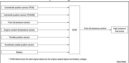
Fuel pressure controlL : System Description
INPUT/OUTPUT SIGNAL CHART
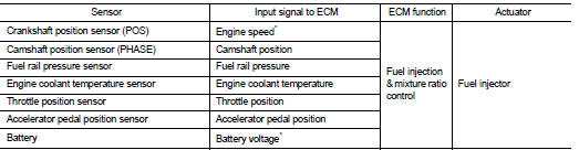
*: ECM determines the start signal status by the engine speed signal and battery voltage.
CVT models
System Description
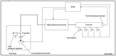
Low fuel pressure control • The low fuel pressure pump is controlled by ECM. The pumped fuel passes through the fuel filter and is sent to the high pressure fuel pump.
• Low fuel pressure is adjusted by the fuel pressure regulator.
High fuel pressure control The high pressure fuel pump raises the pressure of the fuel sent from the low pressure fuel pump. Actuated by the camshaft, the high pressure fuel pump activates the high pressure fuel pump solenoid based on a signal received from ECM, and adjusts the amount of discharge by changing the timing of closing the inlet check valve to control fuel rail pressure.
M/T models
System Description
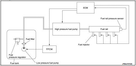
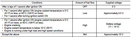
Low fuel pressure control • The low fuel pressure pump is controlled by the fuel pump control module (FPCM) and pumps fuel according to a driving condition. The pumped fuel passes through the fuel filter and is sent to the high pressure fuel pump. FPCM controls the low pressure fuel pump, according to a signal from ECM as shown in the table below.
• Low fuel pressure is adjusted by the fuel pressure regulator.
High fuel pressure control The high pressure fuel pump raises the pressure of the fuel sent from the low pressure fuel pump. Actuated by the camshaft, the high pressure fuel pump activates the high pressure fuel pump solenoid based on a signal received from ECM, and adjusts the amount of discharge by changing the timing of closing the inlet check valve to control fuel rail pressure
 Direct injection gasoline system
Direct injection gasoline system : System Diagram
Direct injection gasoline system : System Description
INPUT/OUTPUT SIGNAL CHART
*1: This sensor is not used to control the engine system under ...
 Electric ignition system
Electric ignition system : System Diagram
Electric ignition system : System Description
INPUT/OUTPUT SIGNAL CHART
*1: CVT models
*2: M/T models
*3: ECM determines the start signa ...
Other materials:
Precaution for Supplemental Restraint System (SRS) "AIR BAG" and "SEAT BELT
PRE-TENSIONER"
The Supplemental Restraint System such as “AIR BAG” and “SEAT BELT PRE-TENSIONER”,
used along
with a front seat belt, helps to reduce the risk or severity of injury to the
driver and front passenger for certain
types of collision. Information necessary to service the system safely is
...
Squeak and rattle trouble diagnoses
Work Flow
CUSTOMER INTERVIEW
Interview the customer if possible, to determine the conditions that exist
when the noise occurs. Use the Diagnostic
Worksheet during the interview to document the facts and conditions when the
noise occurs and any of
customer's comments; refer to DLK-302, &quo ...
Thermo control amplifier
Component Function Check
1.CHECK A/C ON SIGNAL
With CONSULT-III
1. Turn ignition switch ON.
2. Select “AIR CONDITIONER” of “BCM” using CONSULT-III.
3. Select “THERMO AMP” in “DATA MONITOR” mode, and check status under the
following condition.
Is the inspection result normal ...
