Nissan Juke Service and Repair Manual : P1813 4WD mode switch
DTC Logic
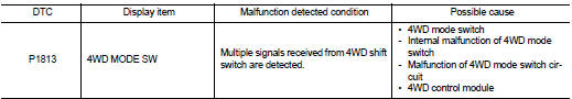
DTC DETECTION LOGIC
DTC CONFIRMATION PROCEDURE
1.PRECONDITIONING
If ŌĆ£DTC CONFIRMATION PROCEDUREŌĆØ has been previously conducted, always turn ignition switch OFF and wait at least 10 seconds before conducting the next test.
>> GO TO 2.
2.DTC REPRODUCTION PROCEDURE
 With CONSULT-III
1. Turn the ignition switch OFF to ON.
2. Turn the 4WD mode switch 2WD⇒4WD-V⇒4WD⇒4WD-V⇒4WD.
3. Perform self-diagnosis for ŌĆ£ALL MODE AWD/4WDŌĆØ.
Is DTC ŌĆ£P1813ŌĆØ detected? YES >> Proceed to diagnosis procedure. Refer to DLN-44, "Diagnosis Procedure".
NO >> INSPECTION END
Diagnosis Procedure
1.CHECK 4WD MODE SWITCH
Check 4WD mode switch. Refer to DLN-45, "Component Inspection".
Is the inspection result normal? YES >> GO TO 2.
NO >> Replace 4WD mode switch. Refer to DLN-92, "Removal and Installation".
2.CHECK 4WD MODE SWITCH CIRCUIT (1)
1. Disconnect 4WD control module harness connector.
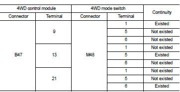
2. Check the continuity between 4WD control module harness connector and 4WD mode switch harness connector.
Is the inspection result normal? YES >> GO TO 3.
NO >> Repair or replace error-detected parts.
3.CHECK 4WD MODE SWITCH CIRCUIT (2)
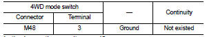
Check the continuity between 4WD mode switch harness connector and ground.
Is the inspection result normal? YES >> GO TO 4.
NO >> Repair or replace error-detected parts.
4.CHECK TERMINALS AND HARNESS CONNECTORS
ŌĆó Check 4WD control module pin terminals for damage or loose connection with harness connector.
ŌĆó Check 4WD mode switch pin terminals for damage or loose connection with harness connector.
Is the inspection result normal? YES >> Replace 4WD control module. Refer to DLN-91, "Removal and Installation".
NO >> Repair or replace error-detected parts.
Component Inspection
1.CHECK 4WD MODE SWITCH
1. Turn the ignition switch OFF.
2. Remove 4WD mode switch. Refer to DLN-92, "Removal and Installation".
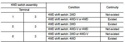
3. Check the continuity between 4WD mode switch harness connector terminals.
Is the inspection result normal? YES >> INSPECTION END
NO >> Replace 4WD mode switch. Refer to DLN-92, "Removal and Installation".
 P1811 power supply circuit for 4wd control module
DTC Logic
DTC DETECTION LOGIC
DTC CONFIRMATION PROCEDURE
1.PRECONDITIONING
If ŌĆ£DTC CONFIRMATION PROCEDUREŌĆØ has been previously conducted, always turn
ignition switch OFF and
wait at least ...
 P181B incomplete selfshut
DTC Logic
DTC DETECTION LOGIC
DTC CONFIRMATION PROCEDURE
1.PRECONDITIONING
If ŌĆ£DTC CONFIRMATION PROCEDUREŌĆØ has been previously conducted, always turn
ignition switch OFF and
wait at least ...
Other materials:
Handling precaution
Nissan Dynamic Control System
ŌĆó The engine torque, engine power, boost, and instantaneous fuel consumption
are provided for information
purposes only. They are not intended to prompt the driver to adjust driving
style. The readings may be
slightly delayed relative to the actual vehicle beha ...
Fuel-filler cap
To remove the fuel-filler cap:
1. Turn the fuel-filler cap counterclockwise 1 to remove.
2. Put the fuel-filler cap on the cap holder A while refueling.
To install the fuel-filler cap:
1. Insert the fuel-filler cap straight into the fuelfiller tube.
2. Turn the fuel-filler cap clockwise 2 unt ...
B2615 blower relay circuit
DTC Logic
DTC DETECTION LOGIC
DTC CONFIRMATION PROCEDURE
1.PERFORM DTC CONFIRMATION PROCEDURE
1. Turn ignition switch ON under the following conditions, and wait for 1
second or more.
CVT models
- Selector lever is in the P or N position
- Do not depress brake pedal
M/T models
- Do no ...
