Nissan Juke Service and Repair Manual : Diagnosis system (air bag)
Description
CAUTION:
• Never use electrical test equipment on any circuit related to the SRS unless
instructed in this Service
Manual. SRS wiring harnesses can be identified by yellow and/or orange harnesses
or harness
connectors.
• Never repair, splice or modify the SRS wiring harness. If the harness is damaged, replace it with a new one.
• Keep ground portion clean.
DIAGNOSIS FUNCTION
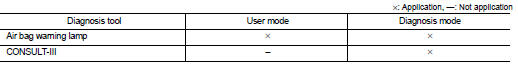
• The SRS self-diagnostic results can be read with air bag warning lamp and/or CONSULT-III.
• The user mode is exclusively prepared for the customer (driver). This mode warns the driver of a system malfunction through the operation of the air bag warning lamp.
• The diagnosis mode allows the technician to locate and inspect the malfunctioning part.
• The mode applications for the air bag warning lamp and CONSULT-III are as per the following items.
On Board Diagnosis Function
ON-BOARD DIAGNOSIS
There are two self diagnosis functions with air bag warning lamp per the following items.
• USER MODE
• DIAGNOSIS MODE
METHOD OF STARTING
• Diagnosis mode changes from user mode to diagnosis mode when changing operation is performed.
• In user mode, when SRS air bag warning lamp is not blinking, changing to diagnosis mode by ignition switch operation is not possible.
• In diagnosis mode, when repair is complete and system is normal, the mode changes to user mode when ignition switch is turned from OFF to ON.
Procedure to Change Diagnosis Mode 1. Turn ignition switch from OFF to ON.
2. SRS air bag lamp turns ON for 7 second and turns OFF, then turn ignition switch OFF within 1second after the lamp turns OFF.
3. After turning ignition switch OFF, wait for 3 seconds or more.
4. Repeat operation 1 to 3 for 2 times so that operation 1 to 3 is repeated for 3times in total.
5. Turn ignition switch from OFF to ON. Diagnosis mode changes.
USER MODE
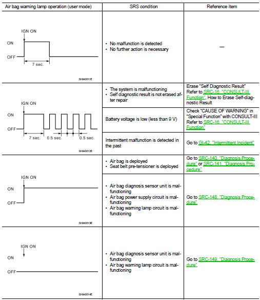
In USER MODE, air bag warning lamp on combination meter blinks when a malfunction is detected and warns the customer (driver).
How to Read Air Bag Warning Lamp 1. Turn the ignition switch from OFF to ON, and check that the air bag warning lamp blinks.
2. Compare the air bag warning lamp blinking pattern with the examples.
Air Bag Warning Lamp Examples
DIAGNOSIS MODE
The diagnosis mode can only be switched when a malfunction is detected in the user mode. Malfunctioning system is indicated according to blinking pattern of air bag warning lamp.
How to Read Air Bag Warning Lamp 1. Follow the procedures of “PROCEDURE TO CHANGE DIAGNOSIS MODE”, and switch to the diagnosis mode.
2. Turn ignition switch ON. Check the blinking pattern of air bag warning lamp.
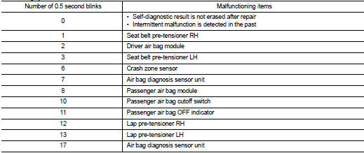
There are 2 blinking patterns for the air bag warning lamp as per the following items.
• Front air bag system: 3 second blink followed by a 0.5 second blink repeated.
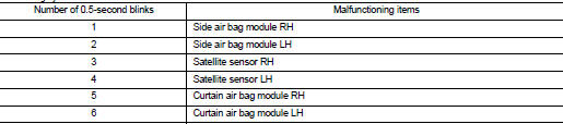
• Side air bag system: Two 1.5 second blinks followed by a 0.5 second blink repeated.
Front air bag system
Side air bag system
How to Erase Self-diagnostic Result After a malfunction is repaired, turn the ignition switch OFF for one second or more, then turn ignition switch ON. The diagnosis mode returns to the user mode. At that time the self-diagnostic result is cleared.
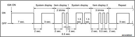
EXAMPLE OF AIR BAG WARNING LAMP OPERATION IN THE DIAGNOSIS MODE
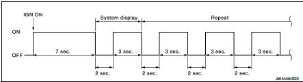
System Normal
When system is normal.
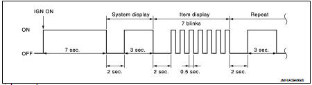
Single System Malfunction • Front air bag system
When air bag diagnosis sensor unit system (Item display 1) is malfunctioning.
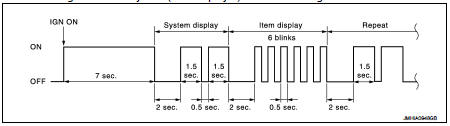
• Side air bag system When curtain air bag module LH system (Item display 1) is malfunctioning.
Multiple Systems Malfunction • Front air bag system When driver air bag module (Item display 1) and air bag diagnosis sensor unit system (Item display 2) are malfunctioning.

• Side air bag system When satellite sensor LH (Item display1) and curtain air bag module LH system (Item display 2) are malfunctioning.
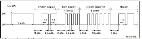
• Front air bag system and side air bag system
When driver air bag module (Item display 1) and satellite sensor RH (Item display2) are malfunctioning.
Consult-III Function
APPLICATION ITEM
CONSULT-III performs the following functions.
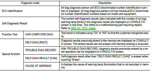
HOW TO ERASE SELF DIAGNOSTIC RESULTS
• “Self Diagnostic Result” A current self-diagnostic result is displayed on CONSULT-III screen in real time.
After the malfunction is repaired completely, no malfunction is detected on “Self Diagnostic Result”.
• “SELF-DIAG [PAST]”
Return to “Self Diagnostic Result” CONSULT-III screen by touching the “BACK” key
of CONSULT-III and
select “Self Diagnostic Result” in SELECT DIAG MODE. Touch “Erase” in “Self
Diagnostic Result” mode.
NOTE
:
If the memory of the malfunction in “SELF-DIAG [PAST]” is not erased, the user
mode shows the system
malfunction by the illumination of the warning lamp even if the malfunction is
repaired completely.
• “TROUBLE DIAG RECORD”
The memory of “TROUBLE DIAG RECORD” cannot be erased.
• “SELF-DIAG RESULT [CAN]” Self-diagnosis result other than “SELF-DIAG RESULT [CAN]” is erased when touching “Erase”.
SPECIAL FUNCTION
CAUSE OF WARNING
This item indicates IGN low or high voltage condition.
The air bag warning lamp blink in user mode when the battery voltage is lowered to the voltage value (less than 9 V or higher to the voltage more than 16V) at which the SRS cannot be operated normally. The air bag warning lamp turns OFF after the battery voltage returns to normal status after blinking.
In such a case, the DTC memory is not performed and changing to the self-diagnostic mode by IGN operation cannot be performed while the air bag warning lamp illuminates. “NO DTC” is displayed even if the malfunctioning parts are checked by CONSULT-III.
This function records the following items.
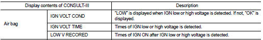
 System
System Diagram
System Description
Supplemental Restraint System (SRS) activates air bag module and seat belt
pre-tensioner when it detects a
frontal collision or a side collision that is more t ...
 ECU diagnosis information
DIAGNOSIS SENSOR UNIT
DTC Index
...
Other materials:
Wiring diagram
ELECTRONICALLY CONTROLLED POWER STEERING SYSTEM
Wiring Diagram
For connector terminal arrangements, harness layouts, and alphabets in a
(option abbreviation; if not
described in wiring diagram), refer to GI-12, "Connector Information/Explanation
of Option Abbreviation".
...
Door mirror system (without intelligent key)
LHD
LHD : Wiring Diagram
For connector terminal arrangements, harness layouts, and alphabets in a
(option abbreviation; if not
described in wiring diagram), refer to GI-12, "Connector Information/Explanation
of Option Abbreviation".
RHD
RHD : Wiring Diagram
For connector termina ...
Back-up lamp switch : Component Inspection
1.CHECK BACK-UP LAMP SWITCH
1. Disconnect position switch connector. Refer to TM-77, "Removal and
Installation".
2. Check continuity between position switch terminals.
Is the inspection result normal?
YES >> INSPECTION END
NO >> Replace position switch. Refer to TM-7 ...
