Nissan Juke Service and Repair Manual : ECU diagnosis information
DIAGNOSIS SENSOR UNIT
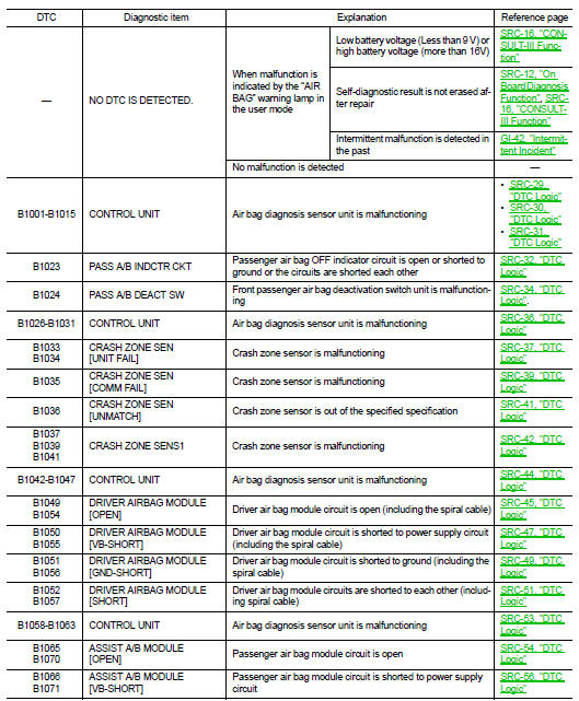
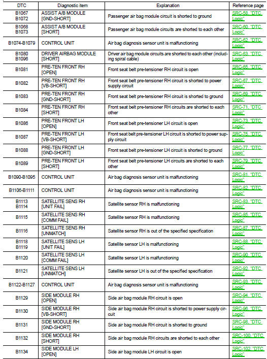
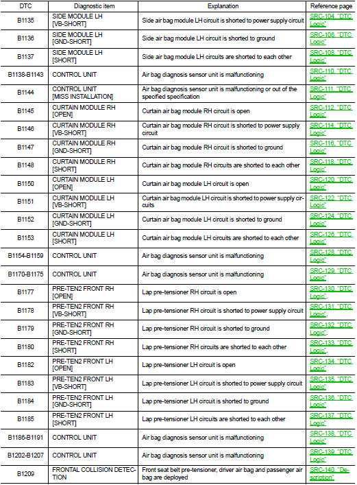
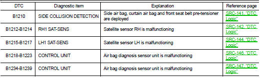
DTC Index
 Diagnosis system (air bag)
Description
CAUTION:
• Never use electrical test equipment on any circuit related to the SRS unless
instructed in this Service
Manual. SRS wiring harnesses can be identified by yellow and/or or ...
 Wiring diagram
SRS AIR BAG SYSTEM
Wiring Diagram
For connector terminal arrangements, harness layouts, and alphabets in a
(option abbreviation; if not
described in wiring diagram), refer to GI-12, "Connect ...
Other materials:
Hood lock
Exploded View
1. Hood lock control cable assembly
2. Hood lock assembly
: Clip
: N·m (kg-m, ft-lb)
: Body grease
Hood lock
HOOD LOCK : Removal and Installation
REMOVAL
1. Remove front center grille. Refer to EXT-18, "Removal and Installation".
2. Remove crash zone sensor. Ref ...
Brake pedal position switch
Component Function Check
1.CHECK BRAKE PEDAL POSITION SWITCH FUNCTION
With CONSULT-III
1. Turn ignition switch ON.
2. Select “BRAKE SW1” in “DATA MONITOR” mode of “ENGINE” using CONSULT-III.
3. Check “BRAKE SW1” indication as per the following conditions.
Without CONSULT-III
...
Precaution for Supplemental Restraint System (SRS) "AIR BAG" and "SEAT BELT
PRE-TENSIONER"
The Supplemental Restraint System such as “AIR BAG” and “SEAT BELT
PRE-TENSIONER”, used along
with a front seat belt, helps to reduce the risk or severity of injury to the
driver and front passenger for certain
types of collision. Information necessary to service the system safely is
...
