Nissan Juke Service and Repair Manual : System
System Diagram
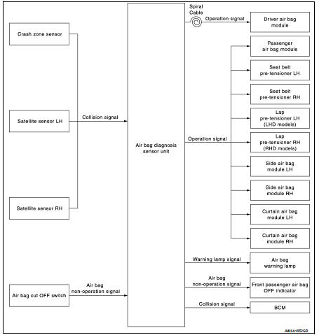
System Description
Supplemental Restraint System (SRS) activates air bag module and seat belt pre-tensioner when it detects a frontal collision or a side collision that is more than the specified limit.
Together with other safety devices, it reduces the impact that occupant receives when vehicle collision occurs.
Air bag diagnosis sensor unit supplies power supply to air bag module and pre-tensioner seat belt when deceleration that is more than the specified limit is detected by G sensor in air bag diagnosis sensor unit, crash zone sensor, satellite sensor.
Air bag module is composed of electric igniter (squib), filter, pyrotechnic material, and gas generating material.
When air bag module receives a signal from air bag diagnosis sensor unit, air bag module ignites pyrotechnic material using electric igniter (squib) so that gas generating material generates high temperature nitrogen gas.
The gas through filter activates air bag. At the same time, pre-tensioner seat belt receives power supply from air bag diagnosis sensor unit, gas generator is activated, and then gas is generated.
Balls in pipe are moved according to generated gas pressure and strike pinion gear on ELR shaft.
ELR shaft rotates and retracts seat belt
AIR BAG DIAGNOSIS SENSOR UNIT FUNCTIONS
Air bag diagnosis sensor unit has the following functions.
• Detects a collision and supplies the energy for deploying air bag and seat belt pre-tensioner.
• Detects and records electrical malfunction in air bag system and seat belt pre-tensioner system, and blinking air bag warning lamp.
• Detects and records the deployment of air bag and seat belt pre-tensioner, and turns ON air bag warning lamp.
• Indicates malfunctioning portion via the number of blinks from the air bag warning lamp in the diagnosis mode.
• Indicates the malfunction record via CONSULT-III.
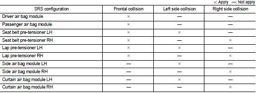
COLLISION MODES
The operation of SRS is different depending on the collision modes applications. For example, the driver air bag module, passenger air bag module, and seat belt pre-tensioner are activated in a frontal collision or side collision.
SRS configurations that are activated for the following collision modes.
 Component parts
Component Parts Location
1. Combination meter
Refer to MWI-4, "METER SYSTEM :
Component Parts Location".
2. Combination switch (spiral cable)
3. Driver air bag module
Crash zone sen ...
 Diagnosis system (air bag)
Description
CAUTION:
• Never use electrical test equipment on any circuit related to the SRS unless
instructed in this Service
Manual. SRS wiring harnesses can be identified by yellow and/or or ...
Other materials:
Radiator cap : Inspection
• Check valve seat (A) of radiator cap.
B : Metal plunger
- Check that valve seat is swollen to the extent that the edge of the
plunger cannot be seen when watching it vertically from the top.
- Check that valve seat has no soil and damage.
• Pull negative-pressure valve to open it, and t ...
C1609 vehicle speed signal
DTC Logic
DTC DETECTION LOGIC
DTC CONFIRMATION PROCEDURE
1.PRECONDITIONING
If “DTC CONFIRMATION PROCEDURE” has been previously conducted, always turn
ignition switch OFF and
wait at least 10 seconds before conducting the next test.
>> GO TO 2.
2.DTC REPRODUCTION PROCEDURE
W ...
Electrical load signal
Description
The electrical load signal (Headlamp switch signal, rear window defogger
switch signal, etc.) is transferred via
the CAN communication line.
Component Function Check
1.CHECK REAR WINDOW DEFOGGER SWITCH FUNCTION
With CONSULT-III
1. Turn ignition switch ON.
2. Select “DATA MONIT ...
