Nissan Juke Service and Repair Manual : Removal and installation
Road wheel tire assembly
Exploded View
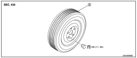
1. Tire assembly
 : N·m (kg-m, ft-lb)
Removal and Installation
REMOVAL
1. Remove wheel nuts.
2. Remove tire assembly.
INSTALLATION
Install in the reverse order of removal.
Inspection
ALUMINUM WHEEL
1. Check tires for wear and improper inflation.
2. Check wheels for deformation, cracks and other damage. If deformed, remove wheel and check wheel runout.
a. Remove tire from aluminum wheel and mount on a tire balance machine.
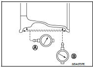
b. Set dial indicator as shown in the figure.
c. Check radial runout, if the lateral deflection (A) or vertical deflection (B) for radial runout value exceeds the limit, replace aluminum wheel.
Limit
Lateral deflection (A) : Refer to WT-9, "Road Wheel".
Vertical deflection (B) : Refer to WT-9, "Road Wheel".
STEEL WHEEL
1. Check tires for were and improper inflation.
2. Check wheels for deformation, cracks and other damage. If deformed, remove wheel and check wheel runout.
a. Remove tire from steel wheel and mount wheel on a tire balance machine.
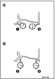
b. Set two dial indicators as shown in the illustration.
c. Set each dial indicator to “0”.
d. Rotate wheel and check dial indicators at several points around the circumference of the wheel.
e. Calculate runout at each point as shown below.
Lateral runout (A): ( 1+2 )/2 Radial runout (B): ( 3+4 )/2
f. Select maximum positive runout value and the maximum negative value. Add the two values to determine total runout.
CAUTION:
In case a positive or negative value is not available, use the
maximum value (negative or positive) for total runout.
Limit
Lateral deflection (A) : Refer to WT-9, "Road Wheel".
Vertical deflection (B) : Refer to WT-9, "Road Wheel".
g. If the total runout value exceeds limit, replace steel wheel.
How to Handle Puncture Repair Agent (Without T-type Spare Tire) infoid
CAUTION:
• Never spill the sealant in the tire during repair.
• If the sealant spills, wipe it out with a waste cloth
.
1. Remove tires. Refer to WT-7, "Removal and Installation".
2. Remove tire from road wheel, using a tire changer.
CAUTION:
• When deflating a tire, cover the valve with a waste cloth to prevent the
sealant from splattering.
• Never spill the sealant in the tire during repair.
3. Dispose of sealant in the removed tire.
CAUTION:
• Wipe out sealant spilled on the road wheel, tire, tire changer, and floor with
a waste cloth.
• Drained sealant or expired sealant returned by the customer must be disposed according to the law and local regulations.
• Fix a tire blowout, if repairable.
NOTE
:
Sealant blocks holes caused by blowouts. These holes may not be found and
repaired, depending on
the level of blowout. Therefore, it is necessary to check tire air pressure
frequently and replace tire with
a new one, if the air pressure is decreasing.
• Replace tire with a new one, if not repairable.
CAUTION:
Never dispose of tires with the sealant contained.
 Periodic maintenance
ROAD WHEEL
Adjustment
BALANCING WHEELS (ALUMINUM WHEEL)
Preparation Before Adjustment
Using releasing agent, remove double-faced adhesive tape from the road wheel.
CAUTION:
• Be careful not ...
 Service data and specifications (SDS)
Road Wheel
ALUMINUM WHEEL
STEEL WHEEL
STEEL WHEEL (EMERGENCY)
Tire Air Pressure
2WD
4WD
...
Other materials:
Primary speed sensor
Exploded View
1. Transaxle assembly
2. O-ring
3. Primary speed sensor
: Always replace after every
disassembly.
: N·m (kg-m, in-lb)
: Genuine NISSAN CVT Fluid NS-2
Removal and Installation
REMOVAL
1. Remove the battery. Refer to PG-124, "Removal and Installation".
2. Remov ...
Door cable
Exploded View
LEFT SIDE
1. A/C unit assembly
2. Intake door lever
3. Intake door link
4. Intake door cable
5. Air mix door cable
6. Upper air mix door rod
7. Upper air mix door lever
8. Lower air mix door lever
9. Lower air mix door rod
10. Air mix door link
A. To A/C control
RI ...
Servicing air conditioner
The air conditioner system in your NISSAN is charged with a refrigerant designed
with the environment in mind. This refrigerant will not harm the earth’s ozone layer.
Special charging equipment and lubricant are required when servicing your NISSAN
air conditioner. Using improper refrigerants ...
