Nissan Juke Service and Repair Manual : Charge air cooler
Exploded View
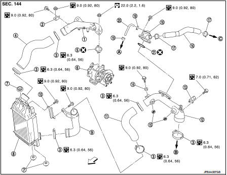
1. Air inlet tube assembly
2. Air inlet tube bracket
3. Clamp
4. Air inlet hose
5. Gasket
6. Turbocharger
7. Mounting rubber
8. Charge air cooler
9. Air inlet tube assembly
10. Air inlet tube bracket
11. Air inlet hose
12. Air inlet tube assembly
13.Turbochager boost sensor
(with intake air temperture sensor 2)
14. Grommet
15. Grommet
16. Air inlet hose
17. Clamp
18. Recirculation valve
19. Clamp
20. Vacuum hose
21. Gasket
A. To vacuum gallery assembly B. To electric throttle control actuator C. To turbocharger
 : Vehicle front
 : N·m (kg-m, ft-lb)
 : N·m (kg-m, in-lb)
 : Always replace after every
disassembly.
Removal and Installation
REMOVAL
1. Remove front bumper. Refer to EXT-12, "Exploded View".
2. Remove radiator core support upper. Refer to DLK-149, "MR16DDT : Exploded View".
3. Remove air inlet hose between air inlet tube and charge air cooler.
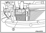
4. Remove charge air cooler (1).
CAUTION:
• Avoid interference between the charge air cooler and radiator.
• When removing charge air cooler, close opening on turbo charger and intake manifold with shop cloth or other suitable material.
INSTALLATION
Install in the reverse order of removal paying attention to the following
points:
• Apply a neutral detergent (fluid) to the joint between hoses and pipes (oil is
not permissible).
• Pay attention to identification mark and direction.
• When installing air inlet hoses and tubes. Refer to EM-31, "Removal and Installation".
Inspection
INSPECTION AFTER REMOVAL
1. Check that the charge air cooler is not full of oil. In that case, clean it with cleaning agent and then let it dry.
2. Check air passages of charge air cooler core and fins for clogging, leaks or deformation. Clean or replace charge air cooler in necessary.
• Be careful not to deform core fins.
• For cleaning procedure of charge air cooler core, refer to CO-19, "Inspection".
 Intake manifold
Exploded View
1. Clamp
2. Water hose
3. PCV hose
4. Clamp
5. Gasket
6. Intake manifold
7. Clamp
8. Vacuum hose
9. Vacuum gallery assembly
10. Clamp
11. EVAP hose
12. EVAP servic ...
 Catalyst
2WD
2WD : Exploded View
1. A/F sensor 1
2. Catalyst convertor shroud upper
3. Gasket
4. Catalyst
5. Catalyst convertor support bracket rear
6. Catalyst convertor bracket (RH)
A. To exhau ...
Other materials:
Door locks/unlocks precaution
• Do not push the door handle request switch with the Intelligent Key held in
your hand as illustrated. The close distance to the door handle will cause the Intelligent
Key system to have difficulty recognizing that the Intelligent Key is outside the
vehicle.
• After locking with the do ...
Sun visors
1. To effectively block blinding sunlight or glare originating from directly ahead, simply swing down 1 the primary sun visor assembly toward the windshield.
2. To block harsh rays penetrating from the side glass, unclip the main sun visor from its central plasti ...
Treadwear
The treadwear grade is a comparative rating based on the wear rate of the tire
when tested under controlled conditions on a specified government test course. For
example, a tire graded 150 would wear one and one-half (1 1/2) times as well on
the government course as a tire graded 100. The rela ...
