Nissan Juke Service and Repair Manual : Turn signal lamp circuit
Component Function Check
1.CHECK TURN SIGNAL LAMP
 CONSULT-III ACTIVE TEST
1. Select “FLASHER” of BCM (FLASHER) active test item.
2. With operating the test items, check that the turn signal lamps is turned ON.
LH : Turn signal lamps (LH) ON RH : Turn signal lamps (RH) ON Off : Turn signal lamps OFF
Is the inspection result normal? YES >> Turn signal lamp circuit is normal.
NO >> Refer to EXL-69, "Diagnosis Procedure".
Diagnosis Procedure
1.CHECK TURN SIGNAL LAMP BULB
Check the applicable lamp bulb.
Is the inspection result normal? YES >> GO TO 2.
NO >> Replace bulb.
2.CHECK TURN SIGNAL LAMP OUTPUT VOLTAGE
1. Turn ignition switch OFF.
2. Disconnect front turn signal lamp connector, side turn signal lamp connector and rear combination lamp connector.
3. Turn ignition switch ON.
4. With operating the turn signal switch, check voltage between BCM harness connector and ground.
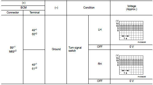
*1: Without Intelligent Key *2: With Intelligent Key
Is the inspection result normal? YES >> GO TO 3.
NO >> GO TO 4.
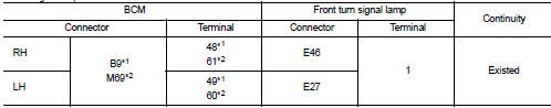
3.CHECK TURN SIGNAL LAMP OPEN CIRCUIT
1. Turn ignition switch OFF.
2. Disconnect BCM connector.
3. Check continuity between BCM harness connector and front turn signal lamp, side turn signal lamp or rear combination lamp harness connector.
Front turn signal lamp
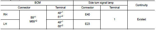
Side turn signal lamp
Rear turn signal lamp
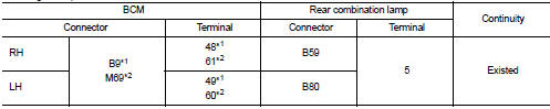
*1: Without Intelligent Key *2: With Intelligent Key
Is the inspection result normal? YES >> GO TO 5.
NO >> Repair or replace harness.
4.CHECK TURN SIGNAL LAMP SHORT CIRCUIT
Check continuity between BCM harness connector and ground.
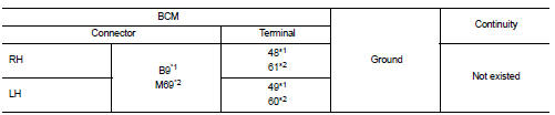
*1: Without Intelligent Key *2: With Intelligent Key
Is the inspection result normal?
YES >> Check each bulb socket for internal short circuit, and if check result is normal, replace BCM. Refer to BCS-93, "Removal and Installation" (with Intelligent Key), BCS-161, "Removal and Installation" (without Intelligent Key).
NO >> Repair or replace harness.
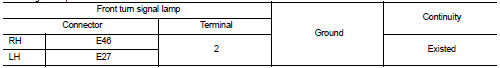
5.CHECK TURN SIGNAL LAMP GROUND OPEN CIRCUIT
Check continuity between BCM harness connector and front turn signal lamp, side turn signal lamp or rear combination lamp and ground.
Front turn signal lamp
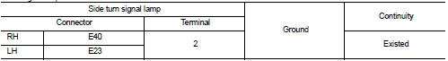
Side turn signal lamp
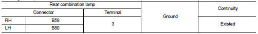
Rear turn signal lamp
Is the inspection result normal? YES >> Check corresponding bulb socket and harness. Repair or replace if necessary.
NO >> Repair or replace harness.
 Light & rain sensor
Component Function Check
1.CHECK LIGHT & RAIN SENSOR
1. Clean light & rain sensor detection area of windshield fully.
2. Turn ignition switch ON.
3. Turn lighting switch AUTO.
4. With the ...
 Hazard switch
Component Function Check
1.CHECK HAZARD SWITCH SIGNAL BY CONSULT-III
CONSULT-III DATA MONITOR
1. Turn the ignition switch ON.
2. Select “HAZARD SW” of BCM (FLASHER) data monitor item.
3. With ...
Other materials:
B210C starter control relay
DTC Logic
DTC DETECTION LOGIC
NOTE:
• If DTC B210C is displayed with DTC U1000, first perform the trouble diagnosis
for DTC U1000. Refer to
PCS-30, "DTC Logic".
• When IPDM E/R power supply voltage is low (Approx. 7 - 8 V for about 1
second), the DTC B210C may be
detected.
...
Removal and Installation
REMOVAL
• Disconnect each joint and mounting.
• Remove heated oxygen sensor 2 with following procedure:
- Using heated oxygen sensor wrench [SST: KV10114400] (A),
removal heated oxygen sensor 2 (1).
CAUTION:
Be careful not to damage heated oxygen sensor 2.
INSTALLATION
Note the follo ...
Wiring diagram
SECURITY CONTROL SYSTEM
LHD
LHD : Wiring Diagram
For connector terminal arrangements, harness layouts, and alphabets in a
(option abbreviation; if not
described in wiring diagram), refer to GI-12, "Connector Information/Explanation
of Option Abbreviation".
RHD
RHD : Wiring D ...
